
General instructions for working on the injection system
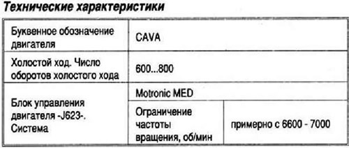
The engine control unit -J623- is equipped with a self-diagnosis function. Before repair, and also for troubleshooting, the fault memory should first be interrogated. Vacuum hoses and connections should also be checked (air leak through non-density). Fuel hoses may only be secured in the engine compartment with spring clips. The use of clamp or screw clamps is not permitted. A voltage of at least 11.5 V is required to maintain the correct operation of electrical components. Do not use silicone sealant. The silicone mass particles sucked into the engine do not burn out and cause the lambda probes to fail. The vehicle is equipped with a fuel cut-off system in the event of a collision. Turning off (through the corresponding relay) fuel pump, it reduces the chance of a car catching fire after a collision. In addition, this system allows you to reduce the time required to start the engine, thereby increasing the convenience of using the car. When the door is opened, the fuel pump turns on for 2 seconds, which allows you to pre-create the necessary working pressure in the fuel system.
Intake manifold
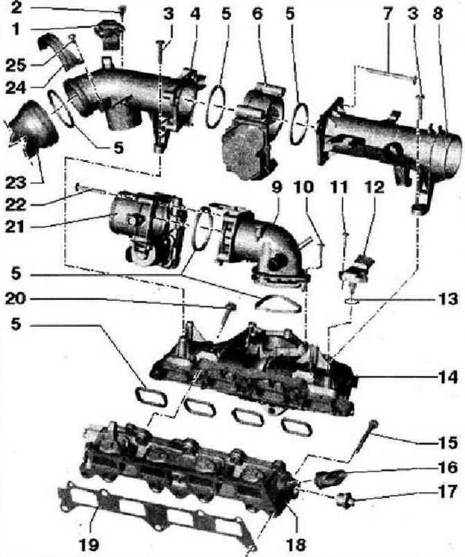
- 1 - Intake air temperature sender 3 -G520- with intake manifold pressure sender 3 -G583-
- 2 - 5 Nm
- 3 - 7 Nm, self-tapping screw. Tightening the fastening screw with a screwdriver is only allowed if the speed of the screwdriver does not exceed 500 rpm and the tightening torque is set to no more than 7 Nm
- 4 - Suction pipe
- 5 - O-ring, replace
- 6 - Regulating flap control unit -J808-. The control flap control unit with plastic housing does not need to be adapted to the engine control unit -J623-. When replacing, delete adaptation parameters and relearn engine control unit -J623-
- 7 - 7 Nm, self-tapping screw
- 3 - Suction pipe
- 9 - Intake manifold pipe
- 10 - 7 Nm, self-tapping screw
- 11 - 5 Nm
- 12 - Intake manifold pressure sender -G71-
- 13 - O-ring, replace
- 14 - Intake manifold, Removing and installing control flap control unit -J808- and throttle flap control unit -J338-
- 15 - 20 Nm
- 1B - Fuel pressure sender -G247-, 22 Nm, check fuel pressure in high pressure area
- 17 - 80 Nm
- 18 - The lower part of the intake manifold. Removing and installing control flap control unit -J80B- and throttle flap control unit -J338- and intake manifold
- 19 - Gasket, replace, observe installation position
- 20 - 20 Nm
- 21 - Air flap unit -J338-. When replacing, delete adaptation parameters in memory and adapt engine control unit -462322- again 7 Nm
- 23 - Pressure pipe from the turbocharger
- 24 - Mounting bracket
- 25 - 7 Nm
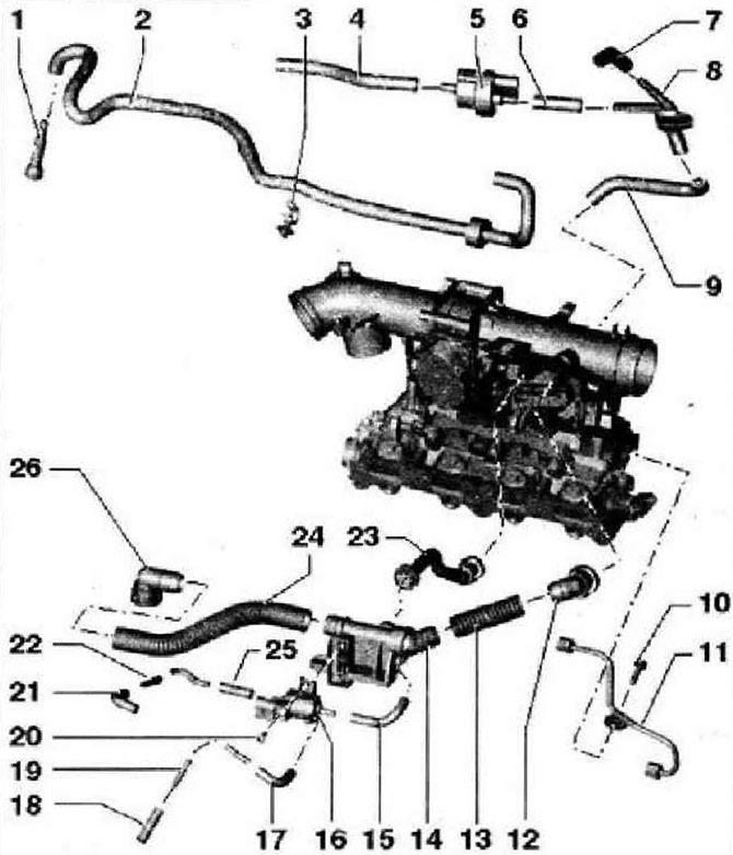
- 1 - Branch pipe for the supply fuel line
- 2 - Fuel hose for the fuel supply line. Low pressure. To high pressure fuel pump
- 3 - Mounting clamp
- 4 - Connecting hose to canister solenoid valve 1 -N80-
- 5 - Solenoid valve 1 for activated charcoal filter -N80-
- 6 - Connecting hose
- 7 - To pressure pipe
- 8 - Connecting tube
- 9 - Connecting hose to the intake manifold
- 10 - 8 Nm
- 11 - Fuel pipe. High pressure. Tightening torque for union nuts: 18 Nm
- 12 - Branch pipe to the suction branch pipe
- 13 - Connecting hose
- 14 - Check valve of the crankcase ventilation system
- 15 - Connecting hose
- 16 - Charge pressure control solenoid valve -N75-
- 17 - Connecting hose
- 18 - Connecting hose to turbocharger
- 19 - Branch pipe
- 20 - 5 Nm
- 21 - Connecting hose to turbocharger
- 22 - Branch pipe
- 23 - Branch pipe of the crankcase ventilation system
- 24 - Connecting hose of the crankcase ventilation system
- 25 - Connecting hose, to charge pressure control solenoid valve -N75-
- 26 - Branch pipe of the crankcase ventilation system, connected to the cover of the distribution mechanism
Fuel rail with injectors
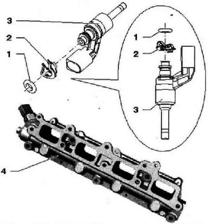
- 1 - O-ring, replace, lightly lubricate with clean engine oil before installation
- 2 - Elastic element, after each removal, replace the lower part of the intake manifold, pay attention to the correct attachment to the injector
- 3 - Injector for cylinder 4 -N33-. Cylinder 1 injector -N30-. Cylinder 2 injector -N31-. Cylinder 3 injector -N32-. With teflon o-ring and back-up washer, after removing the injector, the teflon o-ring and back-up washer must be replaced
- 4 - The lower part of the intake manifold. For removal - Removing and installing control flap control unit -J808- and throttle flap control unit %) 338 intake manifold
Air filter
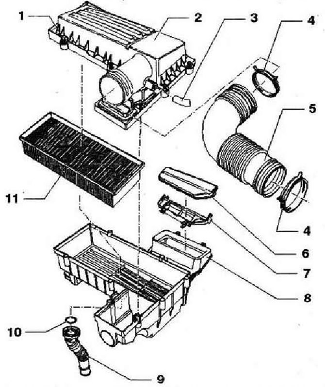
- 1 - 1.6 Nm
- 2 - Upper part of the air filter
- 3 - Vacuum hose. Do not use tools with sharp edges to remove hoses to prevent damage to the nozzle and vacuum hose, replace if damaged. From the camshaft housing
- 4 - Spring clamp
- 5 - Air intake sleeve
- 6 - Overlay
- 7 - Intake air duct
- 8 - Lower part of the air filter with captive mounting bolt, tightening torque: 8 Nm. With suction pipe
- 9 - Water drain pipe. When installing, the arrows on the bottom of the air filter and on the drain pipe must be opposite each other
- 10 - O-ring, replace
- 11 - Filter element
High pressure pump
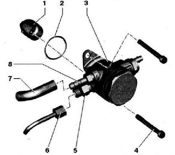
- 1 - Roller tappet, lightly lubricate with engine oil when installing
- 2 - O-ring, replace, lightly lubricate with engine oil when installing
- 3 - High pressure pump with fuel pressure control valve -N276-
- 4 - 20 Nm, tighten bolts evenly
- 5 - Branch pipe. High pressure
- 6 - Union nut, 18 Nm. Strictly observe the safety regulations, when unscrewing, hold the connecting pipe at the high-pressure pump
- 7 - Fuel hose. Low pressure. With spring clip
- 8 - Branch pipe. Low pressure
Visitor comments