
General instructions for working on the ignition system
The engine control unit -J623- is equipped with a self-diagnosis function. A voltage of at least 11.5 V is required to ensure that the electrical components function correctly. During certain checks, the engine control unit -J623- can detect and store a fault. Therefore, at the end of all checks and repair work, it is necessary to interrogate the fault memory and delete the error records that may have been stored in it.
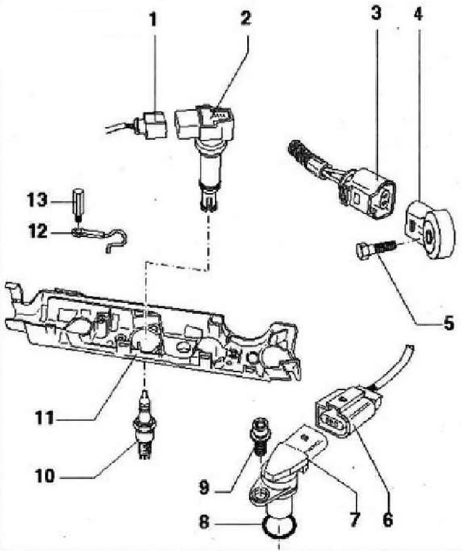
- 1 - Connector, black, 4-pin. Unlock with assembly tool -T10118-
- 2 - Ignition coil 3 with output stage N291-. Ignition coil 1 with output stage -N70-. Ignition coil 2 with output stage -N127-. Ignition coil 4 with output stage -N292-
- 3 - Connector, black, 2-pin, for knock sensor 1-G61-, connector contacts are gold-plated
- 4 - Knock sensor 1 -G61-, connector pins gold-plated, remove compressor to remove
- 5 - 20 Nm, tightening torque affects the operation of the knock sensor
- 6 - Connector, black, 3-pin, sensor Xonna-G40-
- 7 - Hall sender -G4Q-
- B - O-ring, replace if damaged
- 9 - 10 Nm
- 10 - Glow plug, 30 Nm. Remove and install with spark plug wrench -3122 V-
- 11 - Wiring, fasten to the camshaft housing with a torque of 5 Nm
- 12 - Ground wire, unscrew and fasten only with the ignition off
- 13 - 10 Nm, unscrew and screw only when the ignition is off
Visitor comments