
Caution: When carrying out installation work, especially in the engine compartment due to its dense layout, the following rules must be observed. Highways of all types (e.g. fuel, hydraulic, activated carbon absorber, cooling system, air conditioning circuit, brake system, vacuum), as well as electrical wires must be laid as they were originally laid. To avoid damage to hoses, pipes or wires, sufficient space must be provided when working on all moving or hot parts. When the engine is warm, the cooling system is under pressure. Relieve pressure before carrying out repairs. Spring clamps are used for hose connections. When repairing, use only spring clamps. We recommend using hose clamp pliers -VAS 6340- or spring clip pliers -MS 5024A- for installing spring clips. Loosely position the cooling system hoses before installation so that they do not come into contact with other parts (Observe markings on hose and connection).
Body Side Cooling System Components
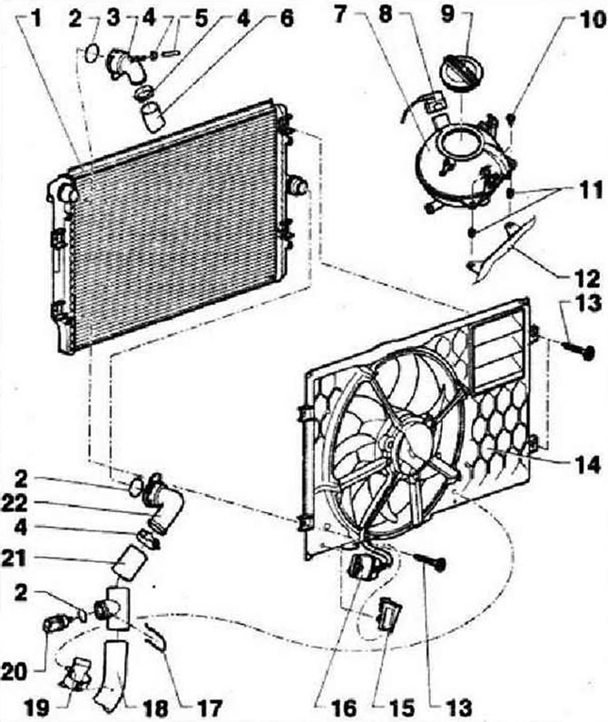
- 1 - Radiator, after replacement, change the coolant
- 2 - O-ring, replace if damaged
- 3 - Branch pipe, to remove, disconnect the clamp
- 4 - Spring clamp. Removing and installing with hose clamp pliers -VAS 6340-
- 5 - Coolant hose
- 6 - Hose of the cooling system, upper, to the fitting on the cylinder head
- 7 - Expansion tank, check for leaks
- 8 - Connector
- 9 - Plug, check for tightness, the safety valve must open at an overpressure of 1.4... 1.6 bar
- 10 - 5 Nm
- 11 - Plastic inserts for fastening screws
- 12 - Bracket
- 13 - 5 Nm
- 14 - Air intake with radiator fan -V7- with radiator fan control unit -J293-. Radiator fan -V7- and air intake must only be replaced as a set when replacing. Heat shields must be fitted to prevent damage to the radiator grille from the thermal energy of the exhaust system. Tightening torque for heat shields: 3 Nm
- 15 - Connector bracket
- 16 - Connector
- 17 - Clamp
- 18 - Hose of the cooling system, lower, to the thermostat fitting
- 19 - Hose routing
- 20 - Radiator outlet coolant temperature sender -G83-
- 21 - Hose of the cooling system, lower, to the thermostat fitting
- 22 - Branch pipe, to remove, disconnect the clip
Engine side cooling components related to the thermostat
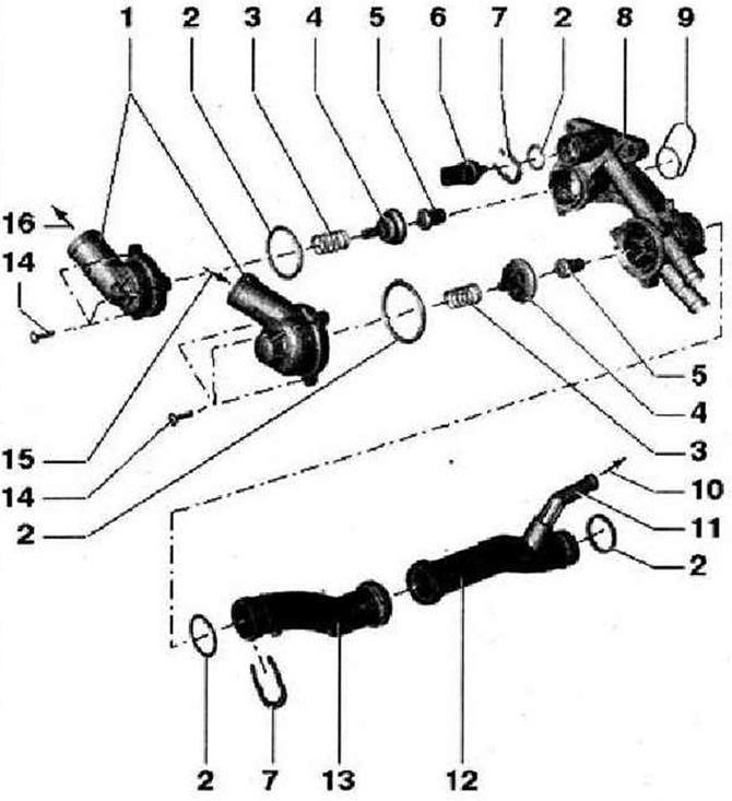
- 1 - Branch pipe
- 2 - O-ring, replace
- 3 - Pressure spring
- 4 - Pusher, do not warp during installation
- 5 - Thermostat. Do not mix up thermocouples! Opening start: thermocouple (bottom figure): 80°С, thermocouple (top drawing): 96°C
- 6 - Coolant temperature sender -G62-, relieve pressure in cooling system before removing if necessary
- 7 - Clamping bracket, check the security of the installation
- 8 - Thermostat housing, 10 Nm
- 9 - O-ring, replace
- 10 - To expansion tank
- 11 - Branch pipe
- 12 - Pipe of the cooling system, to remove, dismantle the thermostat housing, to remove, dismantle the compressor
- 13 - Pipe of the cooling system, to remove, dismantle the thermostat housing, to remove, dismantle the compressor
- 14 - 5 Nm
- 15 - From the bottom of the radiator
- 16 - To the top of the radiator
Connection diagram for cooling system hoses
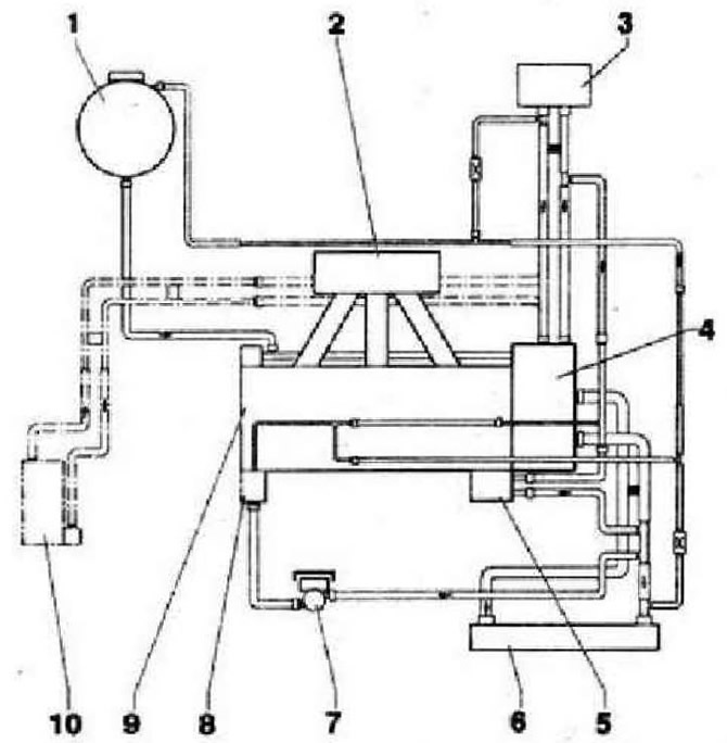
- 1 - Expansion tank
- 2 - Intake manifold
- 3 - heater heat exchanger
- 4 - Thermostat housing
- 5 - Engine oil cooler
- 6 - Radiator
- 7 - Coolant circulation pump -V50-
- 8 - Turbocharger
- 9 - MCC and cylinder block, after replacing the heat exchanger, replace the coolant
- 10 - Auxiliary heater, additional equipment
Visitor comments