



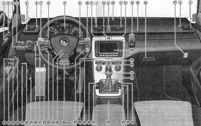
Fig. 1.26. Controls: 1 – door opening handle; 2 – single lock control buttons; 3 – External lighting switch; 4 – Parking brake switch; 5 – deflectors for directed air supply; 6 – regulators of air supply intensity through separate deflectors; 7 – left steering column switch; 8 – controls on the multifunction steering wheel*; 9 – instrument cluster; 10 – right steering column switch; 11 – storage boxes (to open, press the lid); 12 – hazard warning switch; 13 – diffused air supply deflector; 14 – place for mobile phone holder; 15 – Front passenger front airbag; 16 – Main storage compartment handle and lock; 17 – Airbag switch 15; 18 – navigation and/or audio system unit*; 19 – Front passenger seat heating switch-regulator; 20 – HVAC system control unit; 21 – gear shift lever (manual transmission)/mode selector (AT); 22 – storage box or ashtray; 23 – Front window control switches; 24 – Rear window control switches *; 25 – Rear window lock switch *; 26 – outside mirror adjustment unit; 27 – trunk lid opening button; 28 – Fuel filler flap release button; 29 – hood latch release handle; 30 – Instrument and switch illumination intensity regulator; 31 – headlight range adjuster handle; 32 – driver's storage compartment; 33 – Cruise control switch*; 34 – Driver's front airbag; 35 – horn switch; 36 – steering column locking handle; 37 – ignition switch; 38 – Front passenger airbag deactivation switch; 39 – Driver's seat heating switch-regulator*; 40 – stabilization system switch (DSP); 41 – Auto Hold function switch*; 42 – storage box with cup holders; 43 – Rear window blind control switch*; 44 – Parking assistance system switch*; 45 – Tire pressure monitoring system switch
Note: The location of the control instruments varies depending on the specific vehicle model and engine type.
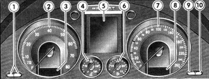
Fig. 1.27. Instrument cluster: 1 – time setting buttons; 2 – tachometer; 3 – hours; 4 – coolant temperature indicator; 5 – Multifunctional display; 6 – fuel reserve indicator; 7 – speedometer; 8 – odometer and resettable trip counter; 9 – reset button for the resettable mileage counter; 10 – Service indicator button
Tachometer
The tachometer needle should never enter the red zone of the scale. The beginning of the red zone of the scale depends on the model of the installed engine.
Watch
To set the current time, use the button located on the right under the tachometer.
Turning the button counterclockwise until it stops sets the hours. A single short turn of the button sets the hours by one hour. Turning the button and holding it in this position sets the hours continuously.
Turning the button clockwise until it stops sets the minutes. A single short turn of the button sets the minutes by one minute. Turning the button and holding it in this position sets the minutes continuously.
Coolant temperature
The indicator works when the ignition is on.
When the ignition is turned on, the signal lamp lights up for several seconds during the operability check.
Low temperature zone
Avoid high engine speeds and do not put heavy loads on the engine.
Normal operating temperature zone
During normal vehicle movement, the needle should be in the middle zone of the scale. Under high engine load and high outside air temperature, the needle may occasionally enter the right zone of the scale. This should not cause alarm until the warning light starts to light.
Note: Installing additional headlights in front of the radiator grille reduces its effectiveness. At high ambient temperatures and high engine loads, there is a risk of engine overheating.
Fuel level indicator
The indicator works when the ignition is on.
The car's fuel tank capacity is approximately 62 liters.
If the indicator has reached the red reserve fuel zone and the warning light is on at the same time, this means that there are still about 8 liters of fuel left.
Speedometer
The device shows the speed of the vehicle.
Odometer
Shows the total mileage of the car, the lower one shows the mileage from a certain moment (trip meter).
The last digit of the lower meter reading represents 100-meter sections.
The lower counter is reset to zero by pressing the button under the speedometer.
Service indicator
When it is time for the next maintenance, the lower counter (daily mileage counter) the speedometer displays one of the following symbols indicating the type of maintenance required:
(The original can be seen on the portal VWmanual.ru)
- oil service - service OEL or - service OIL;
- inspection service - service INSP.
Approximately one minute after the engine has started, the service indicator disappears. You can switch the instrument to the daily mileage indicator earlier by pressing and holding the daily mileage setting button for more than half a second.
The Volkswagen service company that carries out the maintenance resets the service indicator to its original position after completing the work.
If the service was not carried out at a Volkswagen service centre, the service indicator should be reset to its original position in the following order:
- with the ignition off, press and hold the reset button under the speedometer;
- turn the minute button to the right to set the hours. The display will show the message "service".
Note: In any case, it is necessary to set only the required type of maintenance. Otherwise, the time of the required maintenance will be indicated incorrectly. By pressing the setting button, you can select a separate type of maintenance.
Note: Do not perform zero setting between two maintenance intervals as this will cause the instrument to give incorrect readings.
Note: If the speedometer has been replaced, the service indicator must be reprogrammed. This operation must be carried out at a Volkswagen service centre. If the service indicator has not been reprogrammed, the vehicle must be serviced according to the "Service Book" and not according to the service indicator.
Multifunctional pointer
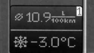
Fig. 1.28. Multifunctional pointer
MFA Multi-Functional Indicator Display (trip computer) provides the following information:
- travel time;
- distance traveled;
- instantaneous specific fuel consumption;
- average specific fuel consumption;
- average speed of movement;
- fuel range remaining;
- outside temperature.
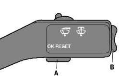
Fig. 1.29. Push-button switches for operating modes of the multifunctional indicator
By repeatedly pressing switch B on the windshield wiper stalk for short periods of time, you can change the display readings when the ignition is on (Fig. 1.29).
Accumulators
The multifunctional indicator is equipped with two automatic storage devices:
- 1 - storage device for storing information on individual trips;
- 2 - storage device for storing information on a group of recent trips.
The numbers "1" or "2" appear in the upper right corner of the display to indicate which drive is currently selected.
To change the storage device, briefly press the A button with the ignition on (see fig. 1.29).
The drive for storing information on individual trips (1) accumulates the following trip data from the moment the ignition is turned on until the moment it is turned off: travel time, distance traveled and amount of fuel consumed. Based on this data, the average travel speed, instantaneous and average specific fuel consumption are calculated.
If the vehicle is not in motion for more than two hours, all data in the storage device is automatically erased.
The accumulator for storing information on the total mileage (2) of the vehicle accumulates all data on any number of trips up to reaching the total values of 99 hours and 59 minutes of vehicle movement, 9999 km of mileage and 999 l of fuel consumed. The accumulated data is used to calculate the average values of specific fuel consumption and speed obtained based on the results of all trips.
When the limit of one of the above values is exceeded, the data in the accumulator for the total mileage is erased and the countdown starts again. This accumulator, unlike the accumulator for individual trips, does not erase the data after two hours of the car's break in movement.
Erasing data from storage devices
You can clear the currently selected drive by holding down the A key for more than two seconds.
When the battery is disconnected, the data contained in both storage devices is erased.
Indications
°C – Outside air temperature.
The display range is from –40°C to +58°C. When the vehicle is stationary or moving at very low speed, the displayed outside air temperature may be slightly higher than the true value due to the influence of thermal radiation from the engine.
At outside temperatures from +4°C to –7°C, the display shows a snowflake icon in addition to the outside temperature (warning of possible black ice).
This icon first flashes for approximately 5 seconds and then remains illuminated until the outside temperature exceeds +4°C or drops below –7°C.
When you draw a conclusion about the possibility of icing of the road based on the outside air temperature, keep in mind that even at a temperature of about +4°C there may be black ice on the road.
min – Travel time.
Accumulator 1 shows the time that has passed since the ignition was turned on or the accumulator was cleared.
Accumulator 2 shows the total time for all individual trips.
The maximum possible display value in both switch positions is 99 hours and 59 minutes. When this value is exceeded, the countdown starts again from zero.
km – Distance traveled.
Everything said about "Trip time" is also true for the "Distance traveled" display. The maximum value that can be displayed is 9999 km.
1/100 km – Instantaneous specific fuel consumption.
Shows current fuel consumption in liters per 100 km.
Instantaneous fuel consumption is calculated every 30 m of travel. With the vehicle stationary and the engine running, instantaneous fuel consumption is shown in liters per hour of operation.
Using instantaneous fuel consumption readings, you can adjust your driving style to your desired fuel consumption.
O/100 km – Average specific fuel consumption.
The average value of specific fuel consumption is displayed, not the current fuel consumption value.
This indicator starts to appear immediately after the ignition is turned on or after covering a distance of 300 meters from the moment when the data in the corresponding storage device was erased. Before this, instead of numbers on the display there are dashes. During movement, the displayed indicator is updated every five seconds.
When accumulator 1 is selected, the display shows the average specific fuel consumption for the current trip. When accumulator 2 is selected, the display shows the average specific fuel consumption for all recent trips.
The amount of fuel consumed is not shown.
Additional information

Fig. 1.30. Message: "Additional information"
When the ignition is on, automatic control of the operation of a number of vehicle systems and devices is carried out.
Malfunctions in the operation of vehicle systems and devices and the degree of necessity to perform certain repairs depending on their importance are divided into primary and secondary. The occurrence of malfunctions is signaled by corresponding text messages and red and yellow light icons on the display of the multifunctional indicator.
If there is a disruption in the normal functioning of certain systems and devices, a corresponding audible warning signal is triggered simultaneously with the appearance of the indication:
- violation of primary importance - three sound signals.
Pictograms of primary importance warn of a danger. Therefore, you should stop and turn off the engine.
Correct the problem. If necessary, seek qualified help.
If several violations of primary importance are noted, the icons appear one after another for approximately 2 seconds each. The icons flash until the violations are corrected.
- minor violation - one sound signal.
Minor violation icons indicate a warning. The corresponding check should be carried out at the earliest opportunity. If several warnings need to be shown, they appear alternately for approximately two seconds.
A secondary violation is indicated only when the primary violation has been corrected.
When both major and minor violations are detected, three warning signals sound.
Mode-measuring service indicator
The service indicator reminds you of the need for maintenance. With a small annual mileage, the inspection service should be carried out every two years.
The special feature of this service indicator is that the maintenance intervals are calculated depending on the specific operating conditions of the vehicle and the driving style of the vehicle.
3000 km before the car reaches the mileage when the next maintenance should be carried out, the indicator displays the following message: "service in 3000 km".
The remaining mileage before service indicator decreases every 100 km.
When maintenance is urgently required, a flashing message appears "service jetzt".
The reminder for the next service disappears approximately 20 seconds after the ignition is switched on. You can also switch on the mileage display earlier by pressing and holding the trip meter setting button for more than 0.5 seconds.
Zeroing should not be performed between two maintenance intervals as the instrument will give incorrect readings.
Visitor comments