



Contents: Replacing antenna wires ↓ General description ↓ Overview of antenna wire installation ↓ Installing a new antenna wire ↓ Repair of wires with cross-section…↓ Wire break in one place ↓
The CAN bus wire is a two-wire wire 1 and 2 with a cross-section of 0.35 mm² or 0.5 mm².
The color coding of the CAN bus wires can be found in the following table
CAN-High bus wire, drive orange/black;
CAN-High bus wire, comfort orange/green;
CAN-High bus wire, Infotainment orange/purple;
CAN-Low wire (all) orange/brown.
Repair of CAN bus wires may be carried out using either a repair wire of suitable cross-section or twisted wires "green/yellow" or "white/yellow" in accordance with the spare parts catalog.
When repairing, both bus wires must have the same length. When twisting wires 1 and 2, the length of the turn must be A=20 mm.
In this case, a section of wire should not be formed, for example, in the area of the weld contacts longer than B=50 mm without twisting the wires.
Wrap the repaired section with yellow tape to indicate that a repair has been made in that area.
Replacing antenna wires
A new repair concept has been developed for repairing antenna cables. Instead of complete antenna cables, connecting cables of various lengths and various adapter cables are now offered as spare parts.
General description
Antenna wires cannot be repaired. If repair is necessary, they should be replaced with connecting wires and adapter cables offered as original spare parts.
These original spare parts are suitable for replacing all antenna wires of any cross-section.
Antenna cable plug housings are available as spare parts in one color only, but can be used to replace antenna plugs of any color.
Replacement of antenna plugs separately in case of repair is not provided.
These wires can be used in all VW models with any cross-section of antenna wires.
All connecting wires and matching cables are suitable for any received and transmitted signals.
This repair concept can also be used for testing and additional equipment.
Overview of antenna wire installation
Example: the antenna wire from the radio to the antenna is damaged. The following wires are needed for repair:
- 1 - adapter cable for connection to the radio. Length about 30 cm.
- 2 - connecting wire, supplied in different lengths.
- 3 - adapter cable for connecting to the antenna. Length about 30 cm.
Installing a new antenna wire
Disconnect the damaged antenna wire plugs from the instruments.
Note: Please note that depending on the vehicle equipment, the total length of the antenna cable may be divided into sections due to the antenna selection control units, radio control units or antenna amplifiers. In each case, only the damaged section must be replaced.
Locate the location of the damaged antenna wire in the vehicle and measure the total length of the damaged antenna wire.
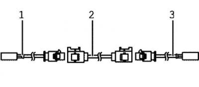
Fig. 7.127. Wires required for repairing the antenna wire
The total length of the antenna cable consists of the length of the required adapter cables 1 and 3, as well as the length of the connecting cable 2 (fig. 7.127).
Subtract 60 cm from the measured total length of the antenna wire to determine the length of the required connecting wire 2.
Purchase the necessary adapter cables 13, as well as connecting wires 2 of the correct length according to the spare parts catalog.
Cut off the damaged antenna wire plugs.
The remainder of the damaged antenna wire remains in the car.
Connect adapter cables 1 and 3 to the vehicle devices.
Route and secure connecting wire 2 directly next to the "serial" wire.
Note: Antenna wires must not be broken or strongly bent. The bending radius must be at least 50 mm.
Connect the connecting wire with the adapter cables.
Conduct a check.
Repair of wires with cross-section up to 0.35 mm²
When repairing wires with a cross-section of up to 0.35 mm², it is imperative to press on new tips using crimping pliers for JPT contacts, or crimping pliers (without head) VAS 1978/12 with installed replacement head for JPT contacts – VAS 1978/91. Due to the small current values in these wires, in the micro- and millirange, incorrectly pressed contacts lead to transition resistances and cause failures or failure of any system. Most often, such contacts are found in the following devices:
- lambda probe;
- rPM sensor;
- mass air flow meter.
By using the JPT contact crimping pliers or crimping pliers (without head) with the JPT contact replacement head installed, a proper connection is made between the crimp contact, the wire and the wire seal (Seal). Use the tool only for its intended purpose.
Note: Repair wires are fitted with standard or gold plated tips. Always use the same tip that was originally used when making repairs.
Crimping a new tip with a wire seal
Insert the JPT contact replacement head into the crimping tool (base of handles).
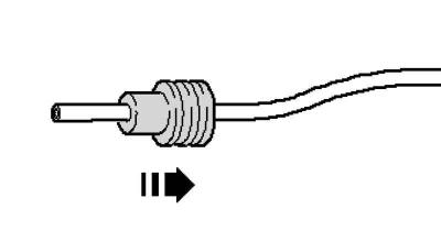
Fig. 7.128. Installing the seal
Place the wire seal on the repair wire (fig. 7.128).
Note: The smaller diameter of the seal should be on the tip side.
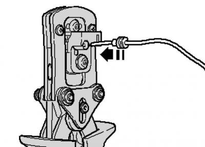
Fig. 7.129. Installing the wire in the crimping pliers
Open the crimping pliers and insert the end of the repair wire into the stripping hole (fig. 7.129).
Squeeze the pliers completely.
Open the pliers again and remove the stripped wire.
Slide the wire seal toward the stripped end so that it ends flush with the wire insulation.
Insert the new crimping tip into the jaws of the crimping pliers.
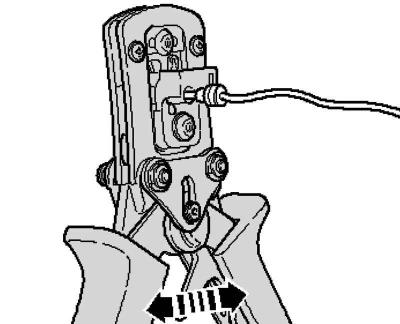
Fig. 7.130. Installing a wire into a crimp terminal
Insert the stripped end of the wire with the seal aligned into the crimp ferrule so that the end is flush with the "Wire-Stop" mark (fig. 7.130).
Crimp the terminal, wire and seal by fully squeezing the crimping pliers.
Open the pliers again and remove the finished tip.
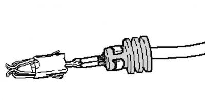
Fig. 7.131. Example of correct wire crimping
A properly performed crimping is distinguished by a clean crimp of the wire and seal in the tip, and on its back there is a stamping, which indicates that the crimping was carried out professionally and with the correct tool (fig. 7.131).
Wire break in one place
Repair site with one crimp sleeve
Release the wire that needs to be repaired (approximately 20 cm on both sides of the repair site).
If necessary, remove the wiring harness wrap with a pocket knife.
Cut out the damaged section of wire using wire strippers.
Note: If both remaining ends of the wire are too short to be repaired with one crimp sleeve due to cutting out the damaged section, use a section of wire of the appropriate length and install two crimp sleeves.
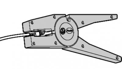
Fig. 7.132. Stripping the wire
Strip 6-7 mm of insulation from the ends of the wire using wire strippers (fig. 7.132).
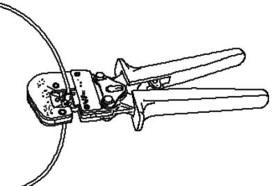
Fig. 7.133. Crimping of a crimping sleeve
Place the crimping sleeve on both stripped ends of the wire and crimp it with a crimping pliers (fig. 7.133).
Note: Make sure to use the correct tip for the used crimping sleeve.
Wire insulation must not be crimped.
After crimping, the crimping sleeve must be seated to prevent moisture from getting inside it.
Attach the attachment to an industrial hair dryer, 220 V/50 Hz.
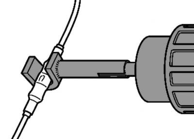
Fig. 7.134. Heating the crimping sleeve
Heat the crimping sleeve with a hair dryer in the longitudinal direction from the middle to the edges until it is completely compressed and glue comes out at the ends (fig. 7.134).
Caution: When shrinking crimp connections, be careful not to damage other wires, plastic parts or insulation with the hot nozzle of the hair dryer.
Caution: Follow the instructions in the hair dryer's operating manual
Note: If it is necessary to repair several wires, a certain distance must be maintained between the crimping sleeves. To prevent the wire bundle from being too thick in circumference after repair, install the crimping sleeves with some offset relative to each other.
Note: If the repaired area was initially wrapped with electrical tape, then after the repair it should be wrapped with yellow electrical tape.
Note: The repaired wiring harness should be secured with a wire tie if necessary to avoid any extraneous noise while driving.
Visitor comments