
Attention: When disconnecting and connecting the battery, be sure to follow the sequence of actions described in the repair manual.
Removing
Disconnect the battery.
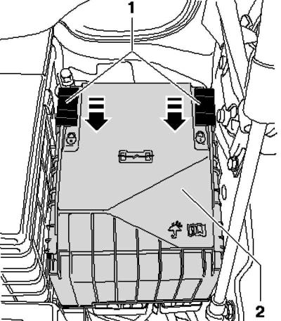
Pic. 7.112. Switch box cover
Install the safety clip 1 in the direction of the arrow and remove the cover of the switching box 2 upwards (pic. 7.112).
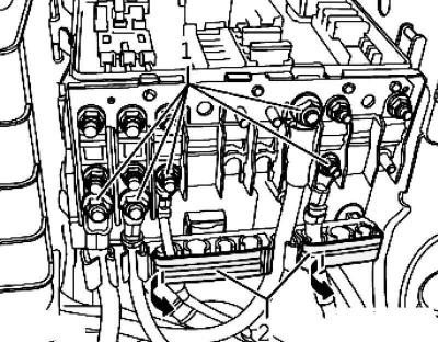
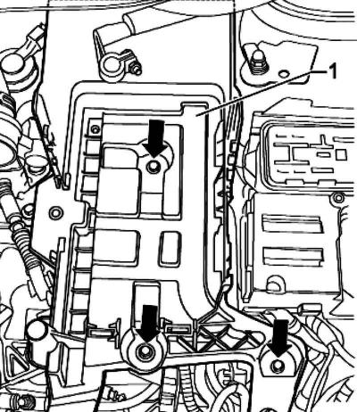
Pic. 7.113. Hex nuts
Loosen hex nuts 1 (pic. 7.113).
Open the 2 cable guide covers on the breakout box.
Remove the cables from the connecting bolts.
Unlock the cables from the guides.
Unscrew the central bolt of the switching unit 1.
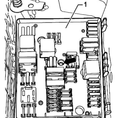
Pic. 7.114. Switching block
Note: When unscrewing the central bolt, the switching unit 1 will be pressed upwards from the holder of the switching unit (pic. 7.114).
Remove the switching unit 1 from the holder upwards.
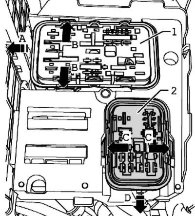
Pic. 7.115. Surface contact housing
Note: To remove the surface contact housing 1, the air filter cover must be removed (only for vehicles with diesel engine) and battery holder (pic. 7.115).
If necessary, remove the air filter cover.
Remove battery.
Pic. 7.116. Battery holder mounting bolts
Unscrew the fixing bolts of the battery holder 1 (pic. 7.116).
Remove the battery holder 1 from the vehicle.
Release the tabs on the holder of the switching unit B and remove the housing with surface contacts by moving the housing 1 to the side A, from the holder of the switching unit (pic. 7.115).
Release the tabs on the holder of the switching unit C and remove the housing with surface contacts by moving the housing 2 forward D, from the holder of the switching unit.
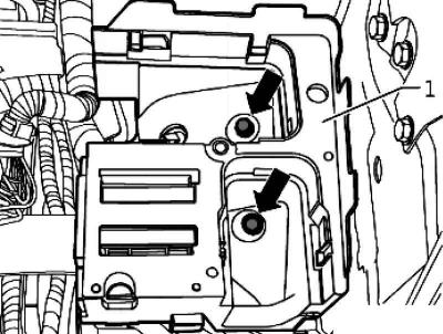
Pic. 7.117. Fastening nuts for the holder of the switching unit
Unscrew the fastening nuts of the holder of the switching unit 1 (pic. 7.117).
Note: The presence of an additional relay box depends on the vehicle equipment.
Remove the holder of the switching box 1, as far as the length of the cables of the additional relay box allows.
Unlock additional relay box 1 sideways from the holder of the switching box (pic. 7.117).
Remove the holder of the switching unit 2 from the vehicle.
Installation
Installation is carried out in the reverse order, paying attention to the following.
Tighten the fixing bolts and nuts to the prescribed torque.
Place cover 2 on the switching unit and slide the safety clip 1 in the direction of the arrow until cover 2 locks into place (pic. 7.112).
Note: Then check that cover 2 of the connection box is properly fixed.
Visitor comments