
Removing the steering gear
Disconnect battery.
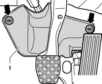
Pic. 5.9. Fastening footwell trim
Remove the trim in the footwell, to do this, unscrew the nuts (pic. 5.9).
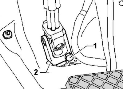
Pic. 5.10. Cardan joint mount
Unscrew the bolt 1 and remove the cardan joint 2 from the steering mechanism (pic. 5.10).
Remove the front wheels.
Loosen the tie rod end nut, but do not remove it yet.
Caution: To protect the threads, leave the nut on the trunnion screwed a few turns.
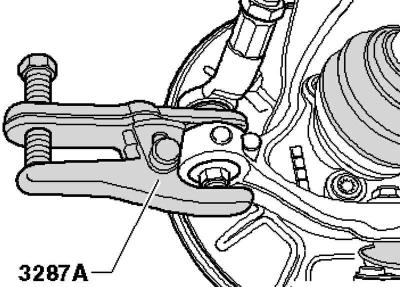
Pic. 5.20. Pressing out the tie rod end
Press the tie rod end out of the wheel bearing housing using a ball joint puller and then unscrew the nut (pic. 5.20).
Remove the bottom noise screen.
Remove the connecting rods from the stabilizer.
Loosen the nuts.
Remove the oscillating support from the gearbox, to do this, unscrew the bolts 13.
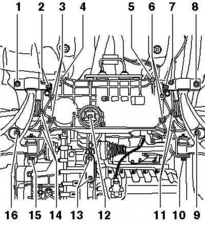
Pic. 5.21. Mounting the steering gear, stabilizer and subframe
Remove the exhaust system mount from the subframe (pic. 5.21).
Remove the bolts from the heat shield.
Vehicles with auxiliary heater
Remove bolts A from the heat shield (pic. 5.22).
Remove fastening 2 from the subframe.
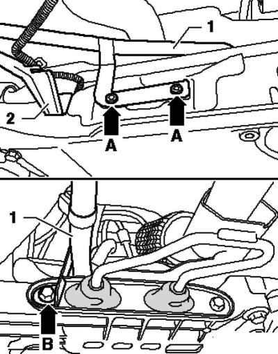
Pic. 5.22. Fastening of the subframe and exhaust pipe of the auxiliary heater
Unscrew bolt B and move the outlet pipe of the additional heater 1 up (pic. 5.22).
Continuation of assembly operations for all vehicles
Remove the heat shield from the subframe.
After that, unscrew the bolts 3, 6, 11 and 14 of the steering mechanism and stabilizer (pic. 5.21).
Fix the subframe and consoles.
Position the engine and transmission stand under the subframe.
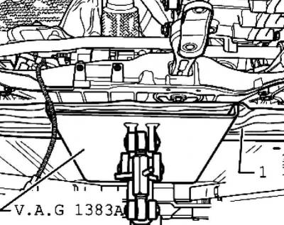
Pic. 5.23. Rack installation
Place, for example, a block of wood 1 between the engine and gearbox support and the subframe (pic. 5.23).
Unscrew bolts 4 and 5 and slightly lower the subframe with consoles. At the same time, keep an eye on electrical wires (pic. 5.21).
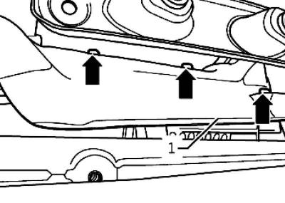
Pic. 5.24. Mounting the heat shield above the steering gear
Remove the heat shield 1 above the steering gear (pic. 5.24).
Unscrew the bolts.
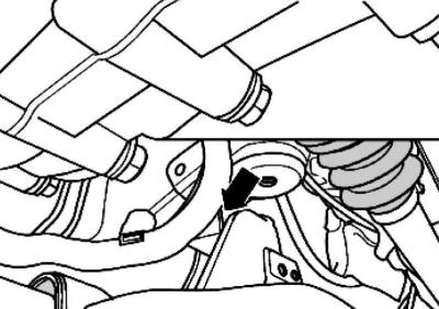
Pic. 5.25. cable box
Unscrew the cable box from the subframe (pic. 5.25).
Unlock all other cable attachment points on the steering box.
Disconnect all electrical connections from the steering gear.
Carefully lower the subframe on the engine and transmission stand.
Separate the steering gear from the subframe and lower it.
Lay the steering gear as shown in the illustration.
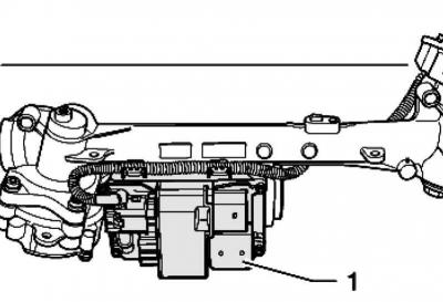
Pic. 5.26. Control block
This prevents damage to the control unit 1 (pic. 5.26).
Steering installation
Installation is carried out in the reverse order.
The threaded bushings of the steering mechanism must enter the holes of the consoles.
Note: Before installing the steering gear, lubricate the steering gear seal with an anti-friction agent such as grease soap.
Note: After installing the steering gear on the universal joint, check that the steering gear seal is not kinked at the mounting plate and that the seal is correctly positioned in the hole in the footwell. Otherwise, water and/or noise may enter.
Note: Keep the sealing surfaces clean.
Note: Before installing the subframe bolts, align the steering gear to the subframe and insert the steering gear and stabilizer bolts.
Install the bottom soundproofing screen.
Screw the cardan joint to the steering gear.
Connect the battery.
Then carry out a basic adjustment of the steering angle sensor using a tester.
After installation, check the position of the steering wheel on a test drive.
If the steering wheel is not straight or a new steering gear is installed, the wheel alignment must be adjusted.
If a new steering gear is installed, it is necessary to adapt the power steering control unit using a tester.
After that, carry out the basic setting of the amplifier control unit using a tester.
Visitor comments