



Caution: It is strictly forbidden to use any other lubricant.
To do this, turn the steering gear in both directions until it stops.
For better clarity, the steering mechanism is shown removed in the figure.
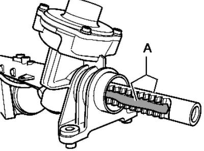
Fig. 5.29. Rack teeth
Apply to rack teeth A and rack rod (from the side where the stop is adjacent) lubrication (Fig. 5.29).
Set the wheels in the straight position.
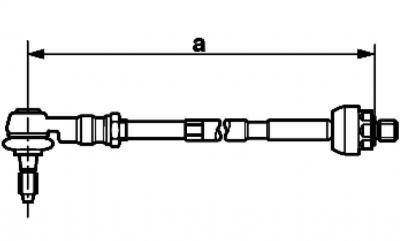
Fig. 5.34. Tie rod and tip size
Screw the tie rod into the tie rod end until dimension A is reached (Fig. 5.34).
Size A = 371 ±1 mm.
Place new clamps and a corrugated boot on the steering rod.
Screw the steering rod into the rack rod and tighten.
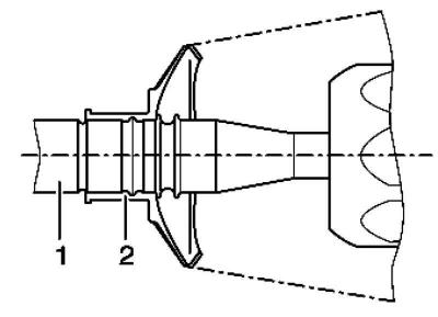
Fig. 5.30. Cover installation diagram
Place the corrugated cover 2 on the steering rod 1 as shown in Figure 5.30.
Place the corrugated cover on the steering gear housing and slide it until it stops.
Using Phaeton steering pliers, crimp the new clamp as shown in the picture.
Further installation is carried out in reverse order.
After installation, check the wheel alignment angles.
Adjust the wheel alignment angles.
Perform a basic installation of the steering angle sensor using.
After this, perform a basic steering setup using a tester.
Visitor comments