



Contents: Removal ↓ Installation ↓
Elements of the lubrication system of four- and five-cylinder engines, except for the 1.6-I engine with the AHL index
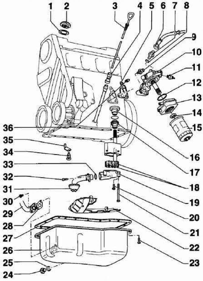
- 1 - O-ring. If damaged, use a new O-ring;
- 2 - lid;
- 3 - dipstick for measuring engine oil level;
- 4 - dipstick retainer. When pumping oil out of the oil pan, it is necessary to remove;
- 5 - O-ring. A new O-ring must be used when installing;
- 6 - Oil supply line, 20 Nm. Oil supply to the turbocharger only on AEB engines;
- 7 - adapter. If there is damage, a new adapter must be used;
- 8 - sealing ring. If there is damage, a new sealing ring must be used;
- 9 - bolt, 25 Nm;
- 10 - Oil filter holder;
- 11 - oil pressure sensor, 25 Nm. If the tightness of the oil pressure sensor installation is broken, a new sealing ring must be used;
- 12 - sealing ring. If there is damage, a new sealing ring must be used;
- 13 - oil heat exchanger. When installing the oil heat exchanger, the surface mating with the flange must be lubricated with a thin layer of sealant, AMV-18810002;
- 14 - nut, 25 Nm;
- 15 - oil filter;
- 16 - cover;
- 17 - oil pump drive gear;
- 18 - oil pump rotors;
- 19 - Oil pump cover with oil pressure relief valve. The oil pressure relief valve opens at a pressure of 5.7–6.7 bar;
- 20 - bolt, 10 Nm;
- 21 - bolt, 25 Nm;
- 22 - oil deflector;
- 23 - bolt. To unscrew the oil pan mounting bolts, you need to use a swivel wrench;
- 24 - oil drain plug;
- 25 - sealing ring;
- 26 - Oil pan. When installing the oil pan, it is necessary to clean the mating surface of the oil pan from traces of the gasket;
- 27 - Oil pan gasket. A new oil pan gasket must be used during installation. Before installing the gasket, apply a layer of D2 sealant to the joints of the sealing flange and the cylinder block. On 1.6-I engines with the AHL code and on five-cylinder engines, the oil pan gasket is missing, and liquid silicone sealant VW-D176404A2 is used instead;
- 28 - Gasket. If damaged, a new gasket must be used.
- 29 - Oil return line. Oil return from turbocharger only on AEB engines;
- 30 - bolt, 10 Nm;
- 31 - oil intake pipe. Before installing the oil intake pipe, it is necessary to clean the mesh filter;
- 32 - bolt, 10 Nm;
- 33 - sealing ring;
- 34 - bypass valve, 27 Nm. Valve opening pressure 2.5–3.2 bar;
- 35 - nozzles for spraying oil onto the lower part of the engine;
- 36 - oil return line shut-off valve, 50 Nm.
Four and five cylinder engines
To remove the oil pan, it is necessary to loosen the power unit mount and, using a lifting mechanism, lift the power unit.
Removal
1. Remove the lower engine splash shield.
2. Drain the engine oil by loosening the oil drain plug about half a turn. Place a container to drain the oil under the drain plug and unscrew the plug completely. If necessary, apply pressure to the plug while unscrewing to prevent premature oil leakage. When the oil has completely drained, screw the oil drain plug back in (see the table "Oil drain plug tightening torques").
3. Remove the poly V-belt.
4. On vehicles with air conditioning, unscrew the tensioner pulley and remove the air conditioning compressor drive belt.
5. Drain the coolant (remove the lower radiator hose).
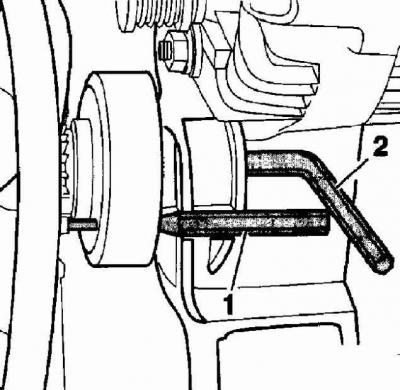
6. Using a steel rod (2) with a diameter of 5 mm, fix the radiator fan pulley from turning and unscrew the radiator fan mounting bolt from the back side. Remove the radiator fan.
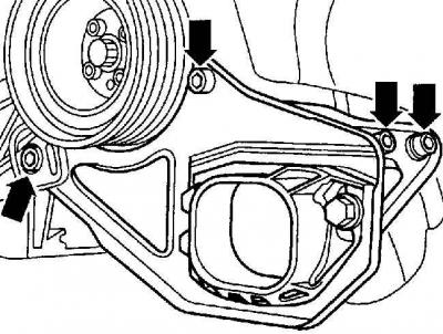
7. Unscrew the engine bracket. Shown with the bracket on a removed engine.
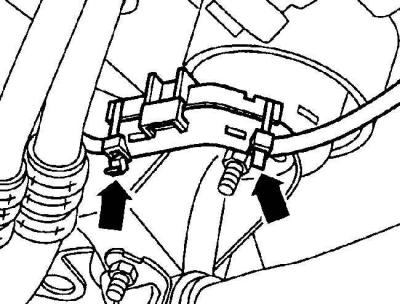
8. Disconnect the wire connection, release the clips and remove the starter wire.
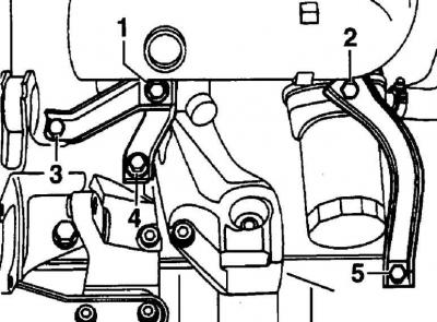
9. If present, unscrew bolts (2 and 5) and remove the bracket located between the oil pan and the intake manifold. Do not unscrew bolts 1, 3 and 4 securing the second bracket.
10. Unscrew the upper part of the left power unit support.
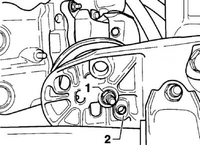
11. Using a marker, mark the location of the threaded connections 1 that secure the bushings 2 to the power unit supports.
12. Unscrew the lower fastening of both powertrain supports.
13. Attach the power unit to the lifting mechanism with slings and lift it so that its lower part just touches the front wall of the body.
14. Remove the left powertrain support.
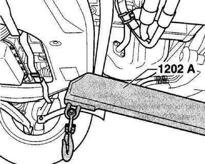
15. Use a jack to support the powertrain support bracket using a wooden block so that it stays in place after the bolts are removed.
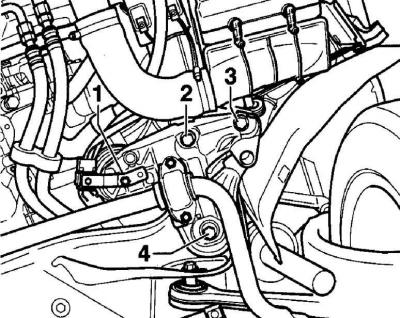
16. Unscrew nuts 1 securing the power unit supports in the lower left and right parts. First, unscrew bolts 2 and 3 from the bracket on the left and right sides, then bolts 4 on the left and right sides.
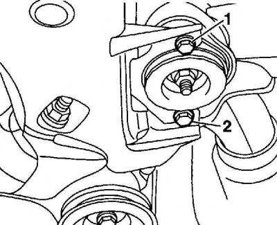
17. Loosen the lower bolt securing the right gearbox support 2 by a few turns, then unscrew the front bolt 1.
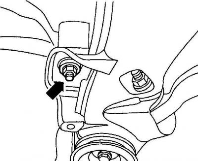
18. Unscrew the nut so that it is level with the end of the bolt.
19. Carefully lower the powertrain bracket using the jack. To avoid displacing the axle, lower and release the bracket from the front.
20. Remove the jack and rotate the stabilizer downwards.
21. Remove the bolts and remove the oil pan from the cylinder block.
Installation
1.6-I engines with AHL code and five-cylinder engines
1. Using a plastic or wooden scraper, scrape the old gasket off the surface of the cylinder block that mated with the oil pan.
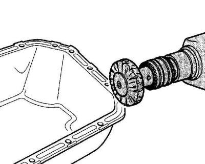
2. Using a rotating wire brush attached to a power drill, clean away the caulk.
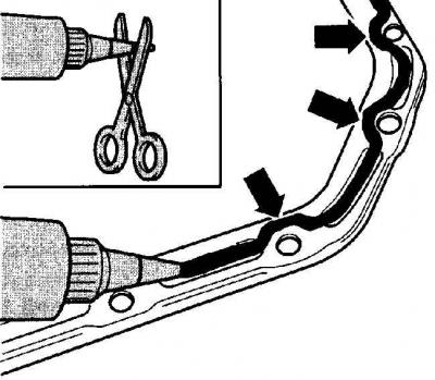
3. Apply a 3mm bead of VW-D176404A2 sealant to the mating surface of the oil pan.
Warning: After applying a layer of sealant to the oil pan, the oil pan must be installed within 5 minutes. The drying time of the sealant is 30 minutes, and only then can engine oil be poured into the engine.
Warning: The sealant layer should only be 3mm in diameter, as if the sealant layer is too thick, excess sealant will get into the oil and may block the mesh filter.
Four-cylinder engines, except for the 1.6-I engine with the code AHL
1. Using a wooden or plastic scraper, clean the mating surfaces of the oil pan and cylinder block of sealant.
2. Before installing the gasket, apply a thin layer of D2 sealant to the junction of the sealing cover and the engine block.
3. Install a new gasket without using sealant.
All engines
Location of powertrain support mounting bolts
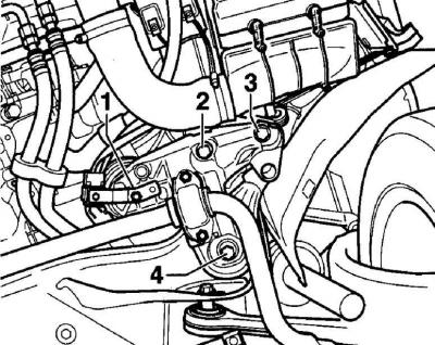
1. Tighten the oil pan mounting bolts evenly and gradually. Do not overtighten the bolts, otherwise the oil pan gasket will be deformed.
2. Lower the engine and remove the lifting gear straps.
3. Using a jack and a wooden block, lift the engine bracket and screw in the bolts on the left and right sides and tighten them to the required torque.
Warning: New bolts must be used to secure the engine bracket.
4. Screw in the engine torque support mount. Tighten all bolts to 25 Nm.
5. Tighten the M10 bolts securing the gearbox support to a torque of 40 Nm and the gearbox support bracket (M8 bolts) to a torque of 25 Nm.
6. Tighten the bracket mounting bolts located between the oil pan and the intake manifold to a torque of 25 Nm.
7. Position the starter wire through the bracket on the oil pan, close the wire holder and secure it with new cable ties.
8. Install the drive belt and radiator fan.
Cars with air conditioning
1. Secure the air conditioning compressor drive belt tensioner roller.
2. Install the air conditioning compressor drive belt.
3. Install the lock bracket.
4. Lower the car.
5. Fill the engine with engine oil. Perform a test drive and check the tightness of the oil pan installation. If necessary, slightly tighten the oil pan mounting bolts.
Visitor comments