



Contents: Transfer case oil ↓ Rear axle final drive oil ↓ Tightening torques of main threaded…↓ Assembly and disassembly of the…↓ Removal and installation the cardan…↓ Removal and installation the viscous…↓ Replacing the front wheel drive…↓ Removal and installation the main…↓ Disassembly and assembly of the…↓ Removal and installation the…↓ Checking the freewheel clutch ↓ Checking the freewheel clutch lock ↓
Torque is transmitted to the rear wheels of the car via a three-part cardan shaft, which connects the transfer case to the viscous coupling. The viscous coupling, acting as a torque divider between the front and rear wheels, transmits torque to the rear axle differential. The rear axle differential is equipped with a freewheel clutch, which allows the rear axle to be disconnected during engine braking. The kinematic diagram of the transmission is shown in Fig. 18.
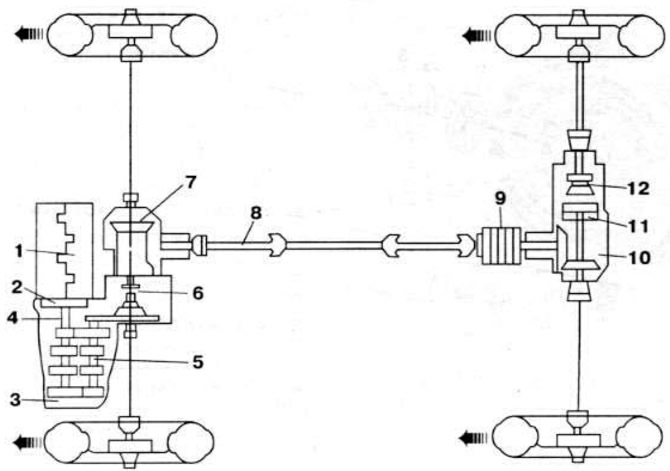
Fig. 18. Kinematic diagram of the vehicle transmission "Passat GT 1.8 G60 Syncro": 1 - engine; 2 - clutch; 3 - gearbox; 4 — primary shaft; 5 — secondary shaft; 6, 12 — differential; 7 — transfer case; 8 - cardan shaft; 9 — viscous coupling; 10 — rear wheel reducer; 11 — freewheel clutch.
Transfer case oil
The crankcase filling capacity is 0.5 l. The oil used is transmission oil, viscosity grade SAE 80 or SAE 75W90. API GL 4 quality class. No oil change is required during the entire service life.
Rear axle final drive oil
The crankcase filling capacity is 0.7 l. The oil used is transmission oil. Viscosity class SAE 80 or SAE 75W90, quality class API GL 4. No oil change is required during the entire service life.
Tightening torques of main threaded connections, kgf·m
Bolts for fastening wheel drives to flanges: 4.5.
Transfer case to gearbox mounting bolts: 4.0.
Bolts for fastening the suspension bracket to the transfer case and to the engine: 4.0.
Bolts for fastening intermediate supports of the propeller shaft to the body: 2.5.
Bolts for fastening the middle part of the propeller shaft to the front and rear parts of the propeller shaft: 4.0.
Bolts for fastening the elastic coupling to the cardan shaft: 4.5.
Assembly and disassembly of the transfer case
The transfer case diagram is shown in Fig. 19.
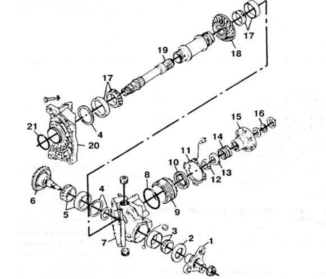
Fig. 19. Transfer case: 1 — cardan shaft drive flange; 2, 10 — oil seal; 3 - rear roller bearing of the driven gear; 4 - adjusting ring; 5 — front roller bearing of the driven gear: 6 — driven gear: 7 — transfer case housing; 8, 21 — sealing ring; 9 - adjusting nut; 11 — adjusting nut retaining ring; 12 - conical bushing; 13 - thrust washer; 14 - pressure spring; 15 — right front wheel drive flange; 16 - retaining ring; 17 - tapered roller bearing of the drive shaft; 18 - drive gear; 19 — drive shaft; 20 — crankcase cover.
To disassemble, remove the transfer case. Loosen the propeller shaft drive flange mounting bolt and remove it. Remove the right front wheel drive flange. Remove the adjusting nut retaining ring. Loosen the adjusting nut, marking its position relative to the transfer case housing. Loosen the transfer case housing connector bolts. Remove the transfer case input shaft. Remove the drive gear with the primary shaft. Remove the driven gear.
For assembly, install the driven and driving gears with the primary shaft in the transfer case housing. Install the propeller shaft drive flange. Lubricate the housing gasket plane with sealant. Replace the housing cover and tighten the bolts to a torque of 2.5 kgf·m. Tighten the adjusting nut to the mark made during disassembly. Install the adjusting nut retaining ring. Install the drive shaft. Install the right front wheel drive flange, conical ring, pressure spring and thrust washer. Use the VW 391 device if necessary. Install the spring washer and retaining ring of the right front wheel drive flange. Install the propeller shaft drive flange fastening bolt with a hexagonal head, lubricating its threads with D6 locking adhesive. and tighten it to a torque of 3.0 kgf·m.
Removal and installation the cardan transmission
The cardan transmission device is shown in Fig. 20.
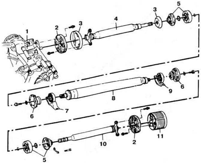
Fig. 20. Cardan transmission: 1 - gearbox with transfer case: 2 - elastic coupling; 3 - protective cover; 4 - front propeller shaft; 5 — constant velocity joint; 6 — flange; 7 - front intermediate support; B - middle cardan shaft; 9 - rear intermediate support; 10 — rear propeller shaft; 11 — viscous coupling.
To remove, disconnect the front part of the muffler and remove it. Remove the heat shield under the propeller shaft. Loosen the bolts securing the rear intermediate support of the propeller shaft. Mark the position of the rear part of the propeller shaft and disconnect it from the constant velocity joint. Loosen the bolts securing the rear part of the propeller shaft to the viscous coupling. Move the middle part of the propeller shaft forward. Remove the rear part of the propeller shaft. Loosen the three bolts securing the front propeller shaft to the flexible coupling. Loosen the three bolts securing the flexible coupling to the transfer case flange. Mark the position of the propeller shaft relative to the flexible coupling. Loosen the bolts securing the front intermediate support to the body. Pull the propeller shaft slightly and loosen the bolts securing the propeller shaft to the flexible coupling. Remove the propeller shaft towards the rear of the vehicle, moving the exhaust pipe slightly to the side.
The installation of the cardan shaft is carried out in the reverse order of removal.
Removal and installation the viscous coupling
When working, refer to Fig. 20, 21 and 22.
To remove, disconnect the rear part of the propeller shaft, marking its position relative to the middle part. Unscrew the centering nut of the viscous coupling with a spark plug wrench. Hold the viscous coupling with a mounting blade. Unscrew the stabilizer of the support bracket and press it down. Remove the viscous coupling.
To install, tighten the centering nut to a torque of 4.5 kgf·m. Install the rear part of the propeller shaft in accordance with the marks made during disassembly.
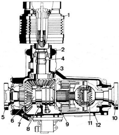
Fig. 21. The device of the main transmission of the rear wheels: 1 — viscous coupling; 2 — gearbox housing; 3 - drive gear adjusting ring; 4 - drive gear; 5 — flange of the left output shaft of the differential; 6 — driven gear of the main transmission; 7 - left differential output shaft; 8 — adjusting washer of main gear bearings; 9 — freewheel clutch; 10 — flange of the right differential output shaft; 11 - differential.
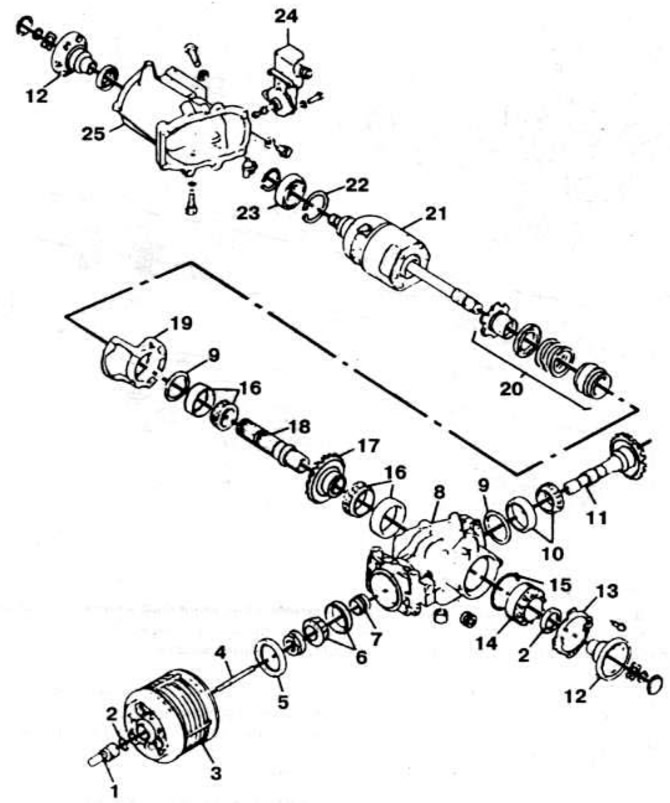
Fig. 22. Details of the main transmission and rear wheel differential: 1 - mounting sleeve; 2, 5 — oil seal; 3 — VK coupling; 4 — pin; 6 - Front roller bearing of the drive gear; 7 — spacer sleeve; 8 — gearbox housing; 9 — adjusting ring: 10 — rear roller bearing of the drive gear; 11 - drive gear; 12 — flange of the left output shaft of the differential; 13 - lock washer; 14 - adjusting nut; 15 - gasket; 16 — driven shaft roller bearing; 17 - driven gear; 18 — input shaft; 19 — clip; 20 — freewheel clutch locking mechanism; 21 — differential with freewheel clutch; 22 — retaining ring; 23 - differential box ball bearing; 24 — pneumatic drive for locking the freewheel clutch; 25 — differential housing.
Replacing the front wheel drive shaft flange seal
Disconnect the front wheel drive shaft from the flange. Remove the retaining ring and spring washer from the flange. Remove the flange. If necessary, use the VW 391 tool. Remove the oil seal using a screwdriver. Install the oil seal in the reverse order.
Removal and installation the main gear and rear wheel differential
The design of the main transmission and differential is shown in Fig. 21 and 22.
Remove the viscous coupling and plug the hole in its housing. Disconnect the right and left rear wheel drive shafts from the flanges. Disconnect the tube from the pneumatic drive of the freewheel clutch lock. Disconnect the rear suspension elements from the gearbox housing. Place a jack under the gearbox housing. Unscrew the bolts securing the gearbox housing. Lower the gearbox housing by 20 cm and disconnect the pneumatic drive hose. Remove the main gear from the vehicle.
The unit is installed in the reverse order.
Disassembly and assembly of the differential of the main transmission of the rear wheels
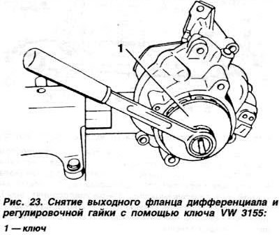
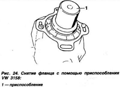
To disassemble, place the unit without the viscous coupling on a support. Drain the oil from the crankcase. Loosen the fastening of the reduction gear pneumatic drive, turn it 90° and remove it from the reduction gear case. Remove the flange of the left differential output shaft (Fig. 23) from the side of the adjusting nut. Remove the lock washer of the adjusting nut. Loosen the adjusting nut, having first marked its position relative to the housing. Loosen the crankcase fastening bolts. Remove the rear differential case. Remove the input shaft with the driven gear, making sure that the locking balls have not fallen out.
Assembly is carried out in the reverse order of disassembly.
Assembly is carried out in the reverse order of disassembly.
Removal and installation the freewheel clutch
The design of the freewheel clutch is shown in Fig. 25.
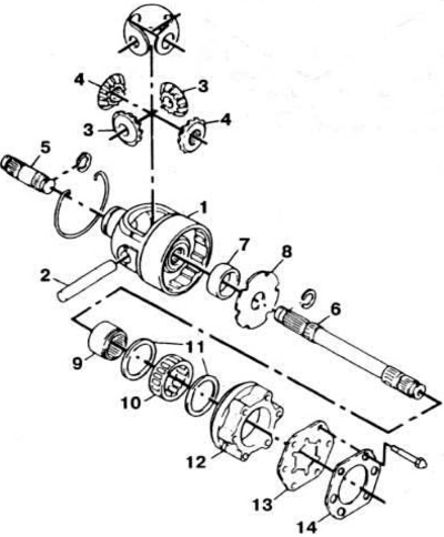
Fig. 25. Rear wheel differential and freewheel clutch parts: 1 - differential box; 2 - satellite axis; 3 - satellites; 4 - axle gears; 5 - right differential output shaft; 6 - left differential output shaft; 7 — spacer sleeve; 8 - external gear disc; 9 — freewheel clutch hub; 10 — roller cage of the freewheel clutch; 11 - thrust washer; 12 — freewheel clutch housing; 13 - internal gear disc; 14 — locking plate.
To remove, secure the differential housing in a vice with soft jaws. Use a lever to remove the retaining ring. Remove the freewheel clutch retaining plate by first unscrewing the bolts. Remove the internal gear disc. Remove the freewheel clutch. Remove the left differential output shaft, external gear disc, and spacer sleeve. Remove the thrust washers. Remove the freewheel clutch hub by turning it to the right. Remove the freewheel clutch locking mechanism housing.
To install, place the locking mechanism housing into the freewheel housing. Install the freewheel hub by turning it to the right. Install the thrust washers. Install the spacer sleeve and external gear disc, aligning the holes in it with the threaded holes in the differential housing. Install the left differential output shaft. Reinstall the freewheel clutch and secure the internal gear disc. Install a new lock plate and bend its two tabs onto the internal gear disc. Tighten the tab bolts to 2.0 kgf·m. Install the retaining ring.
Checking the freewheel clutch
Raise the vehicle. Slowly turn the rear wheels in the forward direction. The wheels should rotate freely. without noticeable resistance. Turn the rear wheels in the reverse direction. At the same time, the transmission should set the front wheels in motion.
Checking the freewheel clutch lock
Run the engine for about half a minute. Raise the car. Turn on the ignition, engage reverse gear and press the clutch pedal. Turn the rear wheels in the forward and backward directions. The wheels should rotate with noticeable resistance and the transmission should rotate the front wheels when the rear wheels are turned in both directions.
Visitor comments