



Remove the clamp securing the protective cover (Fig. 4-83). Remove the clamp securing the cover to the shaft and screw the cover on. Remove the hinge cover by inserting a screwdriver or other suitable object under it, using it as a lever. If the cover does not come off, insert the screwdriver from the opposite side and try again. Remove grease from the hinge parts. Remove the O-ring from the groove.
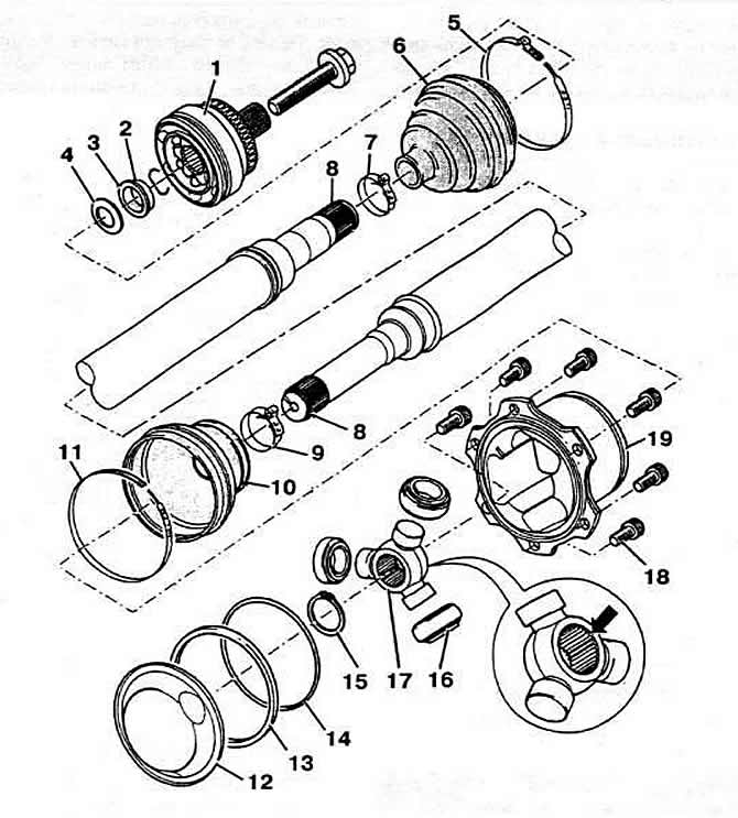
Fig. 4-83. Wheel drive shaft parts:
1 - outer hinge;
2 - retaining ring;
3 — support ring;
4 - spring washer;
5, 7, 9, 11 — cover fastening clamp;
6, 10 - protective cover;
8 — wheel drive shaft;
12 — lid;
13 - rectangular section sealing ring;
14 — O-ring round section;
15 - retaining ring;
16 — rollers;
17 — clip;
18 - bolt with internal multi-faceted recess for key;
19 — hinge housing.
When removing parts, apply installation marks to them, otherwise increased noise from the ball joint may occur while driving.
(The information is presented on the website: www.vwmanual.ru)
Remove the rubber ring from the groove. Holding the hinge housing, remove the wheel drive shaft from the vice, making sure that the hinge rollers do not fall out of the cage. Holding the wheel drive shaft in a vertical position with one hand, slowly move the hinge housing with the other hand. Use a felt-tip pen to mark the position of the rollers relative to the cage. Remove the hinge rollers and place them on a clean surface. Remove the retaining ring. Install the wheel drive shaft in a press. Holding the shaft, press the hinge cage off it. Remove the hinge housing with the boot from the shaft. Clean the shaft and the hinge housing.
To assemble, clamp the wheel drive shaft in a vice with soft jaws. Put a small-diameter clamp for fastening the protective cover of the hinge onto the shaft. Put the cover on the shaft. Put the hinge housing onto the shaft. The chamfer on the hinge sleeve should face the shaft. Put the hinge sleeve onto the shaft according to the previously applied marks, then press it on until it stops. Install the retaining ring, paying attention to its correct position. Install the rollers on the sleeve according to the previously applied marks. Put the hinge housing onto the sleeve with rollers and hold it. Remove the wheel drive shaft from the vice and clamp the hinge housing with the vice.
Install a new rectangular section sealing ring from the repair kit into the groove. The sealing of the connection between the joint and the differential output shaft flange is ensured directly by the rectangular section shape of the sealing ring. For this reason, there is no need to install the joint cover.
Place 90 g of the constant velocity joint grease included in the repair kit into the constant velocity joint. Place 90 g of grease into the back of the joint. Install the protective joint boot in place. Install the flexible boot mounting clamp. Tighten the small diameter clamp with pliers.
Visitor comments