



First, the brush-collector unit is inspected. The height of the brushes and the force of their pressing to the collector by the springs are measured. If the height of the brush is less than 8 mm or its mechanical damage is detected, the brush is replaced. The brushes must move freely, without jamming, in the brush holders. The direction of the force of the brush springs must coincide with the axis of the brush holder. The spring force is checked with a dynamometer. A paper strip is placed between the brush and the collector and the spring is pulled with a dynamometer in the direction of the axis of the brush holder. The dynamometer reading at the moment when the paper strip can be pulled out with light force should be within 1350-2550 gf. If a weakened spring is detected, it is not replaced.
The collector surface must be clean, smooth and without significant burns. If the collector is dirty and slightly burnt, wipe it with a rag soaked in gasoline. A heavily burnt collector is cleaned with sandpaper. After cleaning, abrasive particles are removed by blowing air through the collector. If the burns are not eliminated in this way or there is severe wear of the collector, it is turned on a lathe. The traction relay is checked for a tripping voltage of 8.0 V.
The starter drive must move freely along the shaft without jamming and return to its original position with the return spring. If the drive moves with difficulty, the armature shaft is cleaned of dirt and lubricated with the oil used for the engine.
The axial play of the anchor shaft should be within 0.3±0.15 mm. The radial play of the shaft in the bearings should be almost imperceptible. If the radial play of the shaft is significant, the worn bushings in the starter covers are replaced. New bushings are soaked in motor oil (SAE 30/40) before installation. The anchor and stator are inspected for breaks and traces of burning.
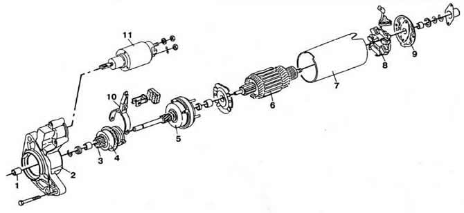
Fig. 8-6. Starter parts with reduction gear:
1 - Front cover bushing;
2 - front cover;
3 — drive gear;
4 — overrunning clutch;
5 — gearbox;
6 - anchor;
7 — housing with stator poles;
8 — brush holder;
9 — back cover;
10 — drive lever;
11 — traction relay.
(View the original article on the resource: vwmanual)
Visitor comments