



The starter motor is tested in idle mode and full braking. Idle mode parameters (rotation speed and current consumption) allow us to judge the quality of assembly and mechanical faults. The presence of defects (tight rotation of the shaft in bearings, etc.) causes an increase in power consumption at idle, as a result of which the idle current increases. and the anchor speed will fall below normal. Electrical faults also appear in idle mode. Thus, an increase in current and a decrease in anchor speed may be a consequence of a mechanical short circuit in the anchor winding, and an interturn short circuit in the excitation winding leads to an increase in the anchor speed. Electrical faults are detected in full braking mode. Full braking mode parameters (torque, current consumption) allow you to determine the condition of the electrical part of the starter. If there is poor contact between the brushes and the collector, the consumed current and torque decrease below the norm. Shorting the armature windings to the housing or shorting the excitation winding leads to a decrease in torque with an increased current consumption against the norm.
The connection diagram during testing corresponds to the starter connection diagram on the vehicle (Fig. 8-7). Starter 1 is switched on by closing the contacts of switch 5. In this case, power is supplied to terminal "50" of the winding(s) of the traction relay and its contacts are closed. As a result, the voltage measured by voltmeter 2 is supplied to the starter electric motor through ammeter 4, starter terminal "30" and closed contacts of the traction relay. The voltage applied to the starter between the starter relay terminal and its housing should be equal to 11.5 V during testing at idle speed. During testing, the starter current and armature rotation speed are recorded. The instrument readings are taken after the starter has been running in idle mode for 20-30 s. The test is considered passed if the consumed current is no more and the rotation speed is no less than the standard values.
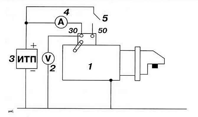
Fig. 8-7. Starter test diagram:
1 - starter;
2 - voltmeter;
3 - DC source;
4 - ammeter;
5 — switch.
It is advisable to conduct the idle test with the brush-collector unit open, observing it visually. There should be no noticeable movement of the brushes in the brush holders, the presence of which indicates increased beating of the collector or protrusion of the insulation above its surface.
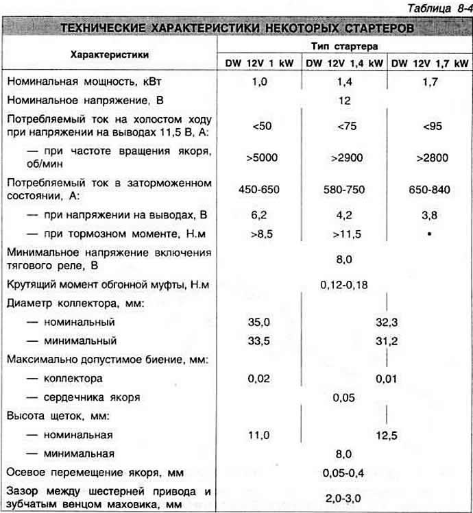
The starter is tested in the full braking mode at a certain supply voltage (Table 8-4). The torque developed by the starter must not be less than a certain value, and the current must not exceed the specified value. The circuit that is assembled when testing the starter in the full braking mode is the same as when testing in the idle mode. Additionally, a load device equipped with a torque meter is required.
Visitor comments