
Follow the detailed view (pic. 8-3), which shows the sequence of removal and installation of parts. When inspecting parts, check:
- the condition of the brushes, their degree of wear, the fit of the brushes to the rings and the pressing force of the springs;
- appearance of slip rings. The slip rings can only be cleaned with a clean rag soaked in petrol or trichlorethylene. Clean slip rings only with fine-grained abrasive paper. It is forbidden to use emery cloth for this purpose;
- bearing condition. Bearings do not require maintenance, as long-life grease is embedded in them;
- appearance of the rotor and stator. Make sure that there are no breaks and signs of burning of their windings.
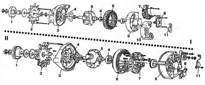
Pic. 8-3. Generator details:
I - brand Valeo;
II - Bosch brand.
1 - pulley;
2 - fan;
3 - cover on the drive side;
4 - bearing;
5 - rotor;
6 - stator;
7 - rectifier block;
8 - brush holder;
9 - cover from the side of slip rings;
10 - plastic casing;
11 - noise suppression capacitor.
Note. It is forbidden to check the electrical characteristics of the generator, in particular the rectifier unit, in circuits with a voltage of more than 14 V. Otherwise, some elements of the generator may fail. Rectifier diodes are sensitive to high temperatures, so soldering when replacing them should be done as quickly as possible using a low-power electric soldering iron.
Rectifier diodes are temperature sensitive. Therefore, when replacing them, solder as quickly as possible using a low-power soldering iron. After repairing the generator, it is advisable to check it on a special stand that allows you to change the rotor speed and generator load. Generators of all types are tested during self-excitation. when the excitation winding is powered by the generator itself (pic. 8-4). A voltmeter 2 is connected to the B+ terminal of the generator 1 and parallel to it through a switch 3 and an ammeter 4 a load rheostat 5 and a battery 6. Turn on the electric motor of the stand and increase (switch contacts 3 open) generator rotor speed. At frequencies close to the frequency of the beginning of the return specified in the technical specification, the generator should be excited. After that, the voltage will increase with increasing speed. If self-excitation does not occur, switch 7 is closed for a short time. In this case, the output D + of the generator through resistor 8 (resistance 3-10 Ohm) connected to the positive terminal of the battery. If in this case the generator is not excited, it is faulty.
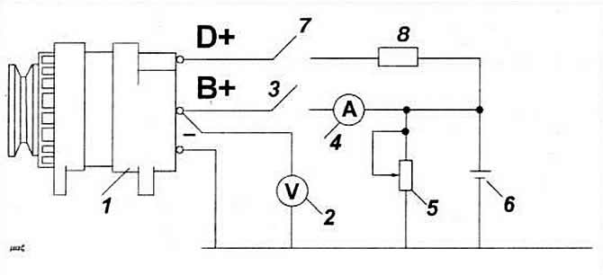
Pic. 8.4. Alternator test circuit:
1 - generator;
2 - voltmeter;
3, 7 - switch;
4 - ammeter;
5 - variable resistor;
6 - battery;
8 - resistor.
After excitation of the generator, the rotor speed is increased to a value. at which the generator voltage is 12 V. In this case, the rotor speed should not be more than the frequency of the start of recoil specified in the technical specification. If the test result is satisfactory, a check is made for the recoil current at a rotor speed of 7000 rpm. To do this, close the contacts of switch 3 and smoothly increase the rotor speed and generator load so that the generator voltage is 12 V. When the speed reaches 7000 rpm, the load current must correspond to the values specified in the technical specification.
Then check the value of the regulated voltage of the generator. To do this, reduce the load current of the generator to the values specified in the technical specification. In this case, the generator voltage should be within 14.2±0.1 V.
Visitor comments