



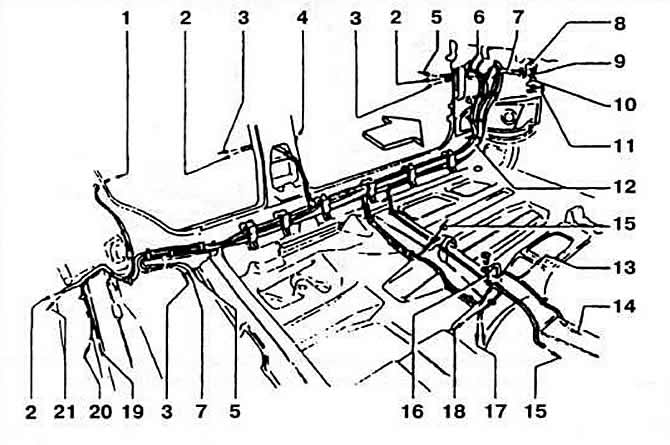
Fig. 8-1. Wiring harness routing on the left side of the body:
1 - to the ceiling light switch in the left door pillar;
2 - to the electric motor of the central door locking system;
3 - to the window lift switch on the left door;
4 - to the ceiling light switch in the left front door pillar;
5 — body position control system wires;
6 — to the electric drive and heating element of the left outside rearview mirror;
7 - ABS brake wire harnesses;
8 - wiring harnesses of the right side of the engine compartment;
9 - Speed controller wire bundles;
10 - headlight wires;
11 - Air conditioning wire bundles;
12 - wire bundles to the rear of the car;
13 — to the switch for sporty and economical driving on cars with automatic transmission;
14 - wire bundles to the automatic transmission;
15 — to the heating elements of the left front seat;
16 — connection to the ground of the wires of the selector lever illumination lamp on cars with automatic transmission;
17 — to the parking brake system indicator lamp switch;
18 - to the ashtray lighting lamp;
19 — to the ceiling light switch in the rear right door pillar;
20 — to the fuel level indicator sensor;
21 - to the rear lights.
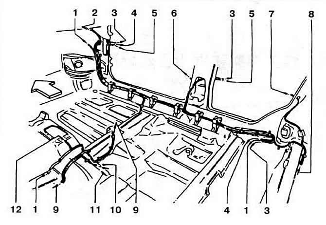
Fig. 8-2. Wiring harness routing on the right side of the body:
1 - wire bundles to the automatic transmission;
2 — to the electric drive and heating element of the right outside rearview mirror;
3 - to the window lift switch on the right door;
4 — wires of the body position control system;
5 — to the electric motor of the central door locking system;
6 - to the ceiling light switch in the right front door pillar;
7 - to the ceiling light switch in the right rear door pillar;
8 - to the ceiling light switch in the left rear door pillar;
9 — to the heating element of the right front seat;
10 — to the parking brake system indicator lamp switch;
11 - to the ashtray light bulb;
12 — to the automatic transmission operating mode switch.
Note: Before performing any maintenance or repair work on electrical equipment, be sure to disconnect the wire from the negative terminal of the battery.
During operation, battery failures may occur due to increased discharge. The reasons may be: slippage of the generator drive belt. Generator malfunction, connection of additional (non-standard) consumers beyond the permissible limits. Increased self-discharge due to severe surface contamination.
The simplest way to determine an increased discharge is to turn on the sound signal. In the case of an increased discharge or poor contact on its terminals, it sounds hoarse.
Visitor comments