



Removal and installation the master brake cylinder
To remove, disconnect the brake fluid level sensor connector. Remove the master cylinder reservoir cap (Fig. 7-17). Remove the brake fluid from the reservoir with a syringe.
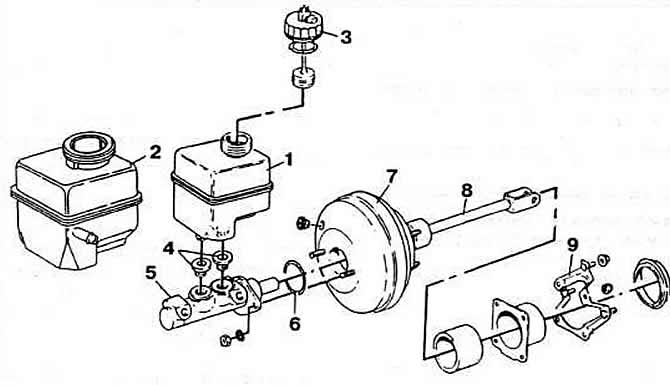
Fig. 7-17. Hydraulic brake drive parts:
1 — reservoir for hydraulic brake drive of vehicles with mechanical clutch release drive;
2 — reservoir for hydraulic brake drive of vehicles with hydraulic clutch release drive;
3 - tank cap;
4 - sealing gaskets;
5 - master brake cylinder;
6 - sealing ring;
7 — brake booster;
8 — pusher;
9 — bracket.
Disconnect the hydraulic lines from the master brake cylinder and plug their openings. Loosen the nuts securing the master cylinder to the brake booster.
If necessary, remove the reservoir from the master cylinder and remove the sealing rings.
Remove the master brake cylinder. Wash the parts with alcohol and check their condition.
When installing, install the reservoir on the master cylinder. Check the presence of a sealing ring on the master cylinder between the cylinder and the brake booster. Install the master cylinder on the brake booster and tighten the mounting nuts to a torque of 2.0 kgf·m. Connect the brake pipes to the master cylinder. Fill the reservoir with brake fluid. Bleed air from the brake hydraulic drive as indicated below.
Install the master cylinder reservoir cap and connect the brake fluid level sensor connector.
The pressure regulator should be checked and adjusted on a loaded vehicle, standing on its wheels, with a full fuel tank. An assistant should take the driver's seat. "Squeeze" the rear suspension several times. Disconnect the hoses from the brake mechanisms of the left front and right rear wheels. Unscrew the fittings for bleeding the brake hydraulic drive from the wheel cylinders and screw in the fittings of the hoses of the control pressure gauges instead.
Remove air from both pressure gauges. While pressing the brake pedal, measure the pressure in the wheel cylinders using the pressure gauges; the values should correspond to those specified in subsection "Features of the device".
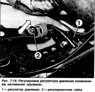
Adjust the tension of the pressure regulator spring depending on the measurement results: if the pressure in the rear wheel brake mechanism is increased, loosen the spring, and vice versa (Fig. 7-18).
If the measured pressure in the rear wheel brake mechanism is not within the specified limits, replace the pressure regulator.
Disconnect the control pressure gauges and remove air from the brake hydraulic system.
Bleeding the brake hydraulic system
Bleeding the brakes is necessary to remove air from the hydraulic drive. Air can get into the hydraulic drive due to depressurization of the system during repair or replacement of individual units, as well as when replacing the brake fluid. If one of the circuits of the brake hydraulic drive is depressurized, air should be removed only from this circuit. The presence of air in the brake drive is indicated by an increased pedal travel and its "softness". It is recommended to use a special unit for bleeding hydraulic drives under pressure. If you do not have one, you can bleed the brake system by pressing the brake pedal. In this case, you will need an assistant. The efficiency of this method is lower, and labor costs are greater than when using a special unit.
When bleeding the rear wheel brakes, vigorously move the pressure regulator lever toward the spring. Bleeding the brake hydraulic drive using a special installation is performed in accordance with the instructions of the manufacturer of the installation used.
Fill the system with brake fluid under a pressure of 2.5 kgf/cm² through the nipple screwed onto the reservoir of the master brake cylinder.
Remove air first from one circuit, then from the other, starting each time from the wheel furthest from the master cylinder, observing the following sequence: brake cylinders of the right rear, left front, left rear and right front wheels.
During bleeding, check and, if necessary, top up the fluid in the reservoir to the norm. Do not use brake fluid that has been drained from the system again. After bleeding the system, put protective caps on the air bleed nipples. After bleeding, press the brake pedal several times to set the pistons to the working position and top up the brake fluid in the reservoir to the normal level. Check the operation of the service brakes during a test drive.
When removing air from the brake hydraulic drive without a special installation, monitor the presence of fluid in the tank, not allowing its bottom to be exposed. Before starting bleeding, eliminate the influence of the vacuum booster by pressing the brake pedal several times.
Remove air first from one circuit, then from the other, starting each time with the wheel furthest from the master cylinder, observing the following sequence: brake cylinders of the right rear, left front, left rear and right front wheels.
Top up the brake fluid in the reservoir to the normal level. Remove the protective caps from the air bleed nipples. Clean the nipples from dust and dirt. Put a transparent tube on the head of the nipple of the brake mechanism of the right rear wheel, and lower its free end into a container filled ⅓ with clean brake fluid. Press the brake pedal. to create pressure in the brake hydraulic system. If there is no resistance when pressing the pedal, slowly and continuously press it until pressing does not require any effort. Unscrew the nipple by ½ a turn with the pedal pressed all the way. After this, the assistant should slowly press the brake pedal and slowly release it, while the liquid along with the air will be forced out of the system through the hose into the container. Repeat this process until the bubbles stop coming out and clean liquid starts coming out of the hose, hold the pedal down and screw the air bleed nipple tightly. Remove the hose and put the protective cap on the nipple.
Repeat the operations for the other wheels.
After bleeding, restore the brake fluid level in the reservoir if necessary. Do not use fluid drained from the system to fill the reservoir, as it is saturated with air, contains a lot of moisture and may be contaminated.
Visitor comments