
Under certain conditions, however, it is possible to disassemble the constant velocity joint in accordance with the instructions given and reassemble it.
Checking the external constant velocity joint
If the car has been driven long enough, then the constant velocity joint has undergone a certain amount of wear. Excessive joint play manifests itself in the form of a beating noise when the accelerator pedal is released, they become noticeable if the engine «pushes». If this can be installed after a long vehicle life, then the constant velocity joint can be replaced with a new one without delay.
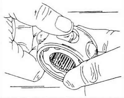
To disassemble the constant velocity joint, you must have a vise to clamp the shaft.
The installation position of the inner sleeve in relation to the ball bearing cage and housing should be marked in an appropriate way.
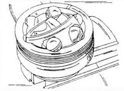
The shaft is clamped in a vice and the sleeve with the ball bearing cage is folded back. Take out the balls one by one. The balls of this joint belong to a certain tolerance group and cannot be replaced.
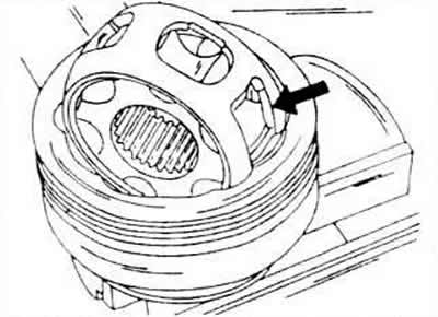
The ball bearing cage is rotated until the rectangular holes shown by the arrow line up with the edges of the housing. Now take out the separator together with the bushing.
The sleeve is rotated until the segment can be pushed into the rectangular bore of the bearing cage and the sleeve can be removed.
All removed parts are checked, ball sticking is also controlled.
The smooth spots are not an indication that the CV joint needs to be replaced with a new one, as they are just ball tracks.
When assembling the hinge of equal angular velocities, it is necessary to act as follows.
Introduce approximately 55 g of grease type G.6.3 into the constant velocity joint.
Insert the separator together with the sleeve into the body.
Insert balls on opposite sides, but make sure they return to their original position in the cage and housing.
Insert a new retaining ring into the constant velocity joint.
Introduce approximately 55 g of grease type G.6.3 onto the inside of the constant velocity joint.
Install a rubber cuff on the constant velocity joint and fasten it with a clamp. For such fastening, special pliers should be used again.
Make sure that the clamp is correctly installed at the other end as well, and carefully place a screwdriver between the collar and the shaft. Due to this, the air trapped in the closed space is released. Tighten the small clamp firmly.
Checking the internal constant velocity joint
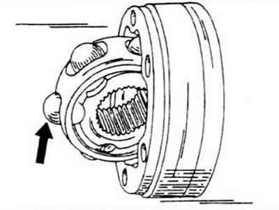
After the constant velocity joint is removed, the bearing cage and the outer ring are installed in one line and the cage is removed in the direction shown by the arrow. Please note that the sleeve, outer ring and six balls are matched to each other and can only be replaced with new ones in a complete set.
The assembly of the hinge of equal angular velocities is carried out in the following sequence.
The ball sleeve is inserted into both grooves of the bearing cage, and then the balls are pressed in. To do this, hold the part and press the balls inward along the circumference.
The bearing bush is inserted into the outer ring in the following way:
The sloping part on the inner side of the bushing must point towards the side of the contact on the drive shaft and towards the large diameter of the outer ring.
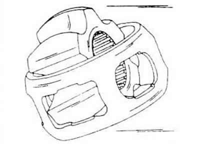
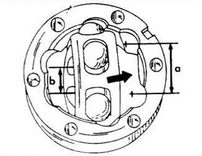
The sleeve, together with the cage and bearings, is inserted perpendicularly into the outer ring as shown in the figure.
Note that in each case the wide groove for the ball (A) and a narrow ball groove (d) in the sleeve are together on the same side when the sleeve is tilted into the outer ring.
The CV joint is pressed onto the shaft, and the shaft must be supported from below.
A new snap ring is inserted into the groove. If required, it is well pressed in using tongs with a water pump.
The hinge of equal angular speeds is installed again.
Visitor comments