
Replacement of the internal constant velocity joint
Secure the drive shaft in a vise.
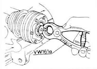
Use pliers to remove the retaining spring ring at the end of the inner CV joint.
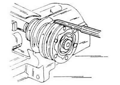
Using a mandrel, carefully knock off the protective cover from the constant velocity joint. In order not to damage the edges of the cover, the mandrel is applied in various places around the circumference.
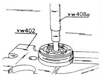
The shaft is mounted under a press and then pressed through a constant velocity joint.
The spring washer is removed from the shaft down. At the same time, pay attention to the principle of installation, since this washer is convex. The larger diameter is adjacent to the constant velocity joint. In addition, it is established that it has an internal gear connection.
The axle shaft should be well cleaned before installing a new constant velocity joint.
The spring washer is pushed onto the shaft in such a way that the bulge is directed upwards, that is, the larger diameter must lie against the constant velocity joint and so that the internal gearing falls on the gearing of the shaft.
The hinge is pressed onto the shaft, and the shaft must be supported from below.
A new snap ring is inserted into the groove. If required, it is well pressed in with the tongs of the water pump.
The hinge is covered with grease G.6.3 (120 grams). Accordingly, each side of the hinge is covered with half portions of this grease and a cuff is put on the drive shaft. It is imperative to use this type of lubricant so that the hinge can work smoothly.
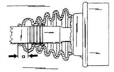
Before putting on the cuff, the size 17 mm is marked on the left shaft. However, this marking must not be scrawled on the paint of the shaft, but must be marked by sticking an adhesive tape. After that, the cuff is put on.
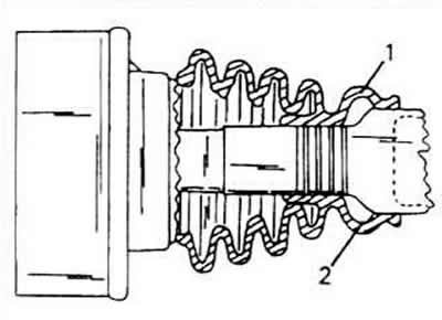
When applying the cuff of the right shaft, it is pressed against the ventilation chamber (1) to the larger diameter of the pipe, so that the vent opening is sure to remain free (2).
External constant velocity joint
Like the inner constant velocity joint, the outer joint can only be replaced with a new one as a set.
As already mentioned, the external constant velocity joint for powerful models differs from the hinge of other car models «Golf». External hinge diameter is 90 mm (81 mm for other models). Keep this in mind when ordering a constant velocity joint.
Removing the constant velocity joint
Remove the fastener clips at both ends of the rubber cuff and press the cuff on the shaft along the constant velocity joint.
Clean the inner surface of the constant velocity joint and find the spring retaining ring in its inner surface.
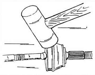
Secure the shaft in a vise with shims and tap the CV joint off the shaft with an aluminum or copper hammer until it can be removed.
Installation of a hinge of equal angular velocities.
The rubber cuff is put on the shaft and moves along it.
Before this installation, half portions of 110 grams of the above grease are pressed into each wall of the constant velocity joint. Only the specified lubricant should be reused.
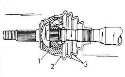
A spring washer with internal gearing is pushed onto the shaft so that the bulge is adjacent to the constant velocity joint, and an adjusting washer is installed on top. On fig. The CV joint is shown in the state of both parts with the CV joint assembled.
Install a new circlip on the shaft, clamp the shaft in a vise and «stuff» CV joint onto the shaft with a copper or aluminum hammer until the circlip can snap into place on the rib in the groove on the inside of the CV joint.
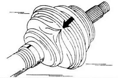
Pull the rubber cuff over the constant velocity joint and secure it with clips. Before closing the cuff, it should be squeezed slightly to squeeze out the incoming air. If, after such an assembly, such «indented» place, then the cuff is loosened again in a place with a small diameter and carefully lifted with a screwdriver so that air enters there and the inlet pressure created there can equalize.
Visitor comments