



Contents: Primary shaft ↓ Secondary shaft ↓ Assembly and installation of…↓ Gearbox housing assembly ↓
Primary shaft
The primary shaft does not need to be adjusted. It is important, however, that the washer found during disassembly is reinserted during assembly.
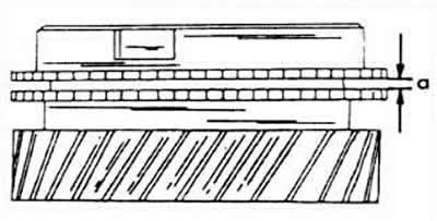
Before assembling the shaft, place the third and fourth gear synchronizing ring on the corresponding gear cone and measure the clearance between the gear and the ring with a thickness gauge. The wear limit is 0.5 mm, while the initial value for the third gear synchronizing ring is 1.15-1.75, and for the fourth gear ring, 1.3-1.9 mm. The same value for the fifth gear synchronizing ring.
If it is necessary to replace the bushing and oil seal ring on the end of the shaft, knock out the parts from the inside using a ten-millimeter round rod. Drive in the new bushing completely. The seal ring is equipped with a plug on the outside. Drive in the part until the plug rests against the flange, then remove the plug. Lubricate the edge of the seal ring with oil.
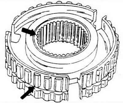
Insert three locking switches into the switching sleeve and push the sliding sleeve onto the sleeve. In case of installation of new parts (the bushing and sliding sleeve are always replaced together) the shift sleeve must be provided with a groove on the end face (top arrow) or a groove along the outer perimeter (outer arrow). Otherwise, you have ordered the wrong part.
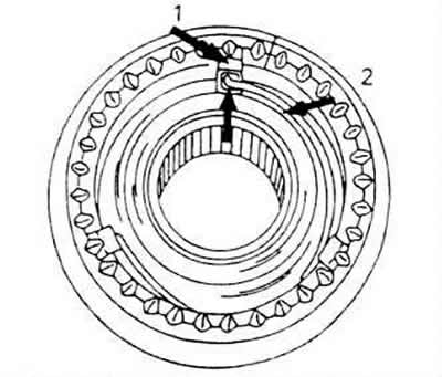
When installing the synchronizer springs, take into account the drawing and install the springs as shown, i.e. shift the end of the spring lying on the opposite side by 120° in relation to the other spring. Note that the bevel of the inner toothed rim of the sleeve should be located towards the third gear pinion. On the other side of the sleeve, on its outer edge, there is a groove that should be directed towards the fourth gear.
Slide the third gear gear together with the needle roller bearing onto the shaft (well oiled) and press the synchronizer in place, but at the same time turn the synchronizing ring so that the groove is in line with the locking switches. Check the chamfer on the inside of the bushing again (it should be facing the third gear).
To secure the synchronizer, use a new snap ring, but make sure that the ring fits perfectly into the groove.
Install the fourth gear pinion together with the needle roller bearing (well oiled) and press firmly.
Press the ball bearing together with the compensation washer into the gearbox housing. Make sure that the closed side of the bearing faces the fourth gear pinion.
Secondary shaft
The fifth gear pinion of the secondary shaft is located above the gearbox housing. The housing contains a needle roller bearing.
Both secondary shaft tapered roller bearings will be destroyed if pressed out. In this case, replace the bearing cap together with the bearing at one end and the outer working ring located in the bearing housing at the other end. If this work is performed, the adjustment must be re-done.
A number of changes were made to the gearbox designed for this engine, affecting the shaft configuration. The changes concern (let's list just a few of them) increasing the diameter of the teeth of the fixed gear of the fourth gear, the appearance of an additional groove on the gear of the third gear and the already mentioned parts intended for fastening the gear of the fourth gear, increasing the spring retaining rings. When ordering new parts, it is best to always provide the gearbox number.
If you are reusing old parts, lubricate the bearing separators with oil and insert the shaft into the bearing housing. Finally, install the bearing cap. Turn the cap correctly so that the reverse gear stop nozzle is on the same side as the reverse shaft.
When installing new bearings, they must be heated in an oil bath to a temperature of 100°C and the corresponding ends pressed onto the shaft. In this case, the inner ring of the lower bearing must be well supported.
Check the synchronizing rings and mount the synchronizer parts. The degree of wear is 0.5 mm. The gap between the newly installed parts is 1.1-1.7 mm.
Move the thrust washer 12 so that the flange faces the bearing cover.
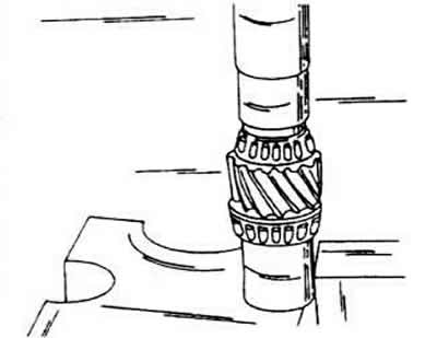
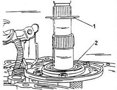
Heat the first-second gear synchronizing sleeve 8 together with the synchronizing ring 9 to 120°C and press it onto the shaft using a piece of pipe. The teeth of the synchronizing sleeve should face the first gear pinion.
Mount the reverse shaft together with the reverse gear. If necessary, the shaft must be driven in.
Press or hammer the inner ring of the needle roller bearing 7 for the second gear onto the shaft and slide it all the way up to the needle roller bearing gear.
Slide the second gear pinion 6 onto the needle roller bearing.
Heat up the third gear pinion 5 and press it in from the end of the shaft so that its flange faces the second gear pinion. The spring retaining ring should snap into the groove.
Measure the axial clearance of the third gear pinion. Usually, take a snap ring and insert it into the groove (the gear is pressed tightly). Since there is no suitable selection of snap rings available, a measurement is taken using a thickness gauge. Using the resulting measurement, a snap ring can be ordered. To adjust the gap, snap rings of different thicknesses are available (2.5-3.0 mm). Please note that the snap rings designed for this engine's transmission have a larger diameter (at the same thickness).
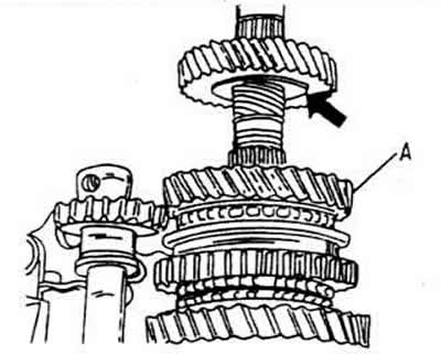
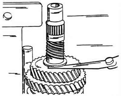
Fit fourth gear pinion 3 - flange upwards - and position the new snap ring 2. Press it well into the groove. As already mentioned, the 2L gearbox uses a second snap ring.
Press the bearing with a deep groove onto the shaft. The wide flange of the inner ring of the bearing should face the press punch.
Install the preloading fixture (it can only be installed in one position), and then tighten it until it stops.
Before installing the fork block, insert the spring into the hole in the clutch housing. It is located in front of the gears.
Reinsert the power plugs in the reverse order of removal.
The reverse shaft must be aligned according to the instructions. To do this, screw the screw into the threaded hole of the reverse shaft and insert the shaft into its guide hole so that the line drawn mentally through the head of the screw passes in the middle between both holes for the screw in the gearbox housing. In this position, drive the shaft until it stops towards the bearing cover.
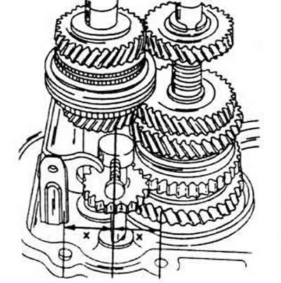
Install the gearbox housing as described below.
Assembly and installation of differential
Heat the new differential bearings to 100°C and press them onto the bearing journals. Suitable pipe sections can be used for this. A pipe section should also be placed under the differential case to support it on the other side.
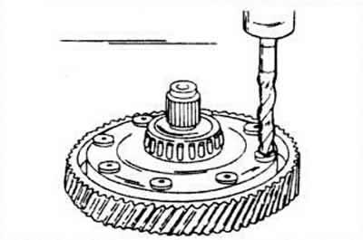
If you are replacing a large pinion, you will need to drill out the rivets (12mm). This will not cause any problems as each rivet is punched in the centre. Then knock out the rivets.
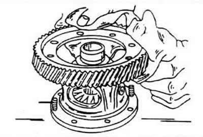
To install the large pinion gear, heat to 100°C and press onto the differential case. Two guide screws (A) must be screwed into the case on opposite sides to guide the pinion during pressing. Use a thick rag when installing the flat bevel gear. Order new special screws, lock washers and nuts (N 171 498 088 A, repair kit) and nuts up to a torque of 70 Nm.
If only the satellites were removed and the flat bevel gear was not unscrewed, both sawed off rivets must be replaced with the two aforementioned screws.
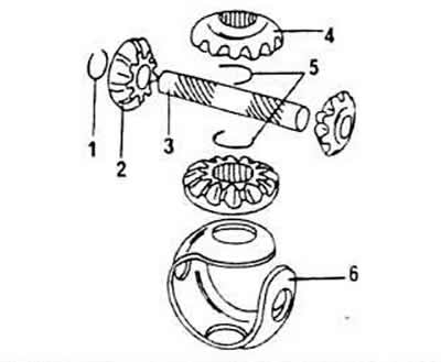
1 - snap rings on the original shaft there are no snap rings)
2 - satellite bevel gears
3 - differential gear axle
4 - side gear
5 - internal spring retaining rings
6 - ball bearing separator
Install the bevel gears together with the ball bearing separator. Carefully tap in the differential axle, avoiding damage to the separator holes.
Insert the side gears into the hole to rotate the bevel gears into the desired position.
Insert the input shafts, and then determine the thickness of the inner snap rings as follows.
Press the flange installed on the input shaft side against the differential axle and move the gear towards the wall of the differential box.
Insert the snap ring, making sure it is not pinched anywhere. If it is, use a smaller snap ring.
Similarly, position the snap ring on the other side and insert it.
The differential is installed in the reverse order of dismantling. The differential must be inserted before both flange shafts are installed.
Gearbox housing assembly
The gearbox housing is assembled in the reverse order of disassembly, however the following aspects must be taken into account.
Make sure the reverse shaft is in the correct position.
Screw two M8 studs into the bearing shield, which will serve as guide elements for the gearbox.
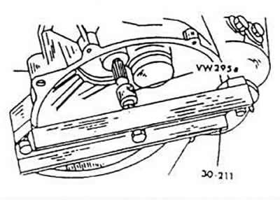
Screw the gearbox bridge and put on the housing. Tap the housing with a rubber mallet. Do not forget to insert the compensation washer for the bearing.
Screw in the reverse shaft screw. It must be tightened (20 Nm) using a special socket set, since it is a screw with a "Torx" head.
Screw in the reverse light switch.
Tighten the deep groove bearing clamp plate to 15 Nm.
Tighten the screws inserted between the two halves of the housing to a torque of 25 Nm. These two screws are shorter in length and fit under the shift shaft screw.
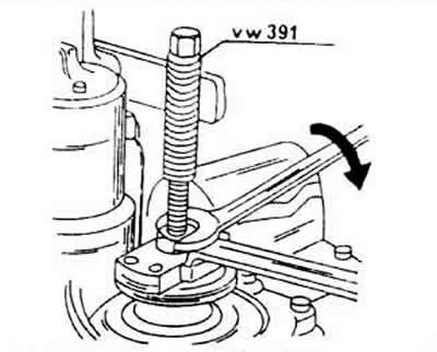
When installing the drive side flange, position the tool as shown in the figure. Place the retaining ring on the shaft and drive the ring in with a piece of pipe of the appropriate diameter until it fits into the groove. Drive in the cap.
Heat the fifth gear to 100°C and drive it onto the shaft with the groove facing up. In this case, install the spring retaining ring. In this gearbox, you need to pay attention to the special retaining ring again.
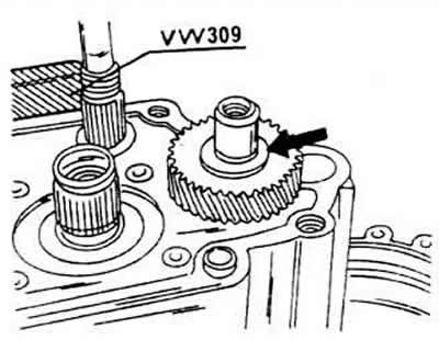
Install the synchronizing shift sleeve together with the gear and shift fork and fit the new lock plate.
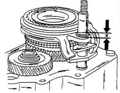
Screw the shift tube into the shift fork clockwise and unscrew it again until it protrudes by 5 mm. Measure the size at the location shown in the figure. When removing the socket wrench, do not pull out the shift bar, otherwise the shift on the inside will fail and the gearbox will have to be disassembled again. If necessary, to hold the shift lever in its position while the wrench is removed, insert a screwdriver from the side through the slot.
Apply D6 thread protector to the new shift sleeve screw and tighten it to 150 Nm using an M12 Allen key (a key with an internal polyhedron designed for 12 prongs). Engage reverse and fifth gear to lock the shaft.
Set the shift forks to idle and install the shift shaft. To do this, align the gearbox horizontally and secure the tin housing with a piece of electrode wire so that it cannot turn.
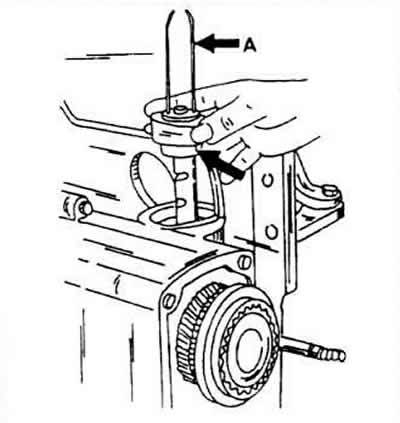
Fit the spring and cap and tighten the cap using a socket wrench to a torque of 50 Nm.
Lubricate the locking screw of the selector shaft with AMV 188 200 03 protective agent and insert it. Tighten the screw to a torque of 40 Nm.
Now adjust the fifth gear fork as follows. The adjustment must be done carefully to prevent the gear from jumping out in the future.
Check the size (x) again. It should be 5 mm.
Mount the lever on the shift shaft and engage fifth gear by pulling the shaft out completely and turning it to the left.
Using the engagement fork, slightly lift the synchronizer sliding sleeve to eliminate all gaps between the parts.
Check the quality of engagement of the sliding clutch with the gear teeth. The overlap should be 1 mm. Otherwise, move the shift tube.
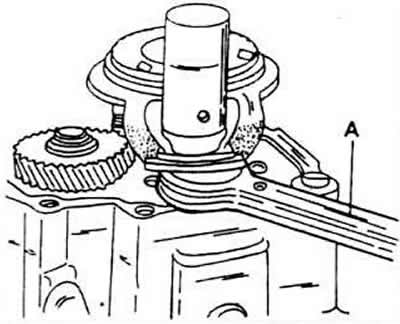
Install the locking plate. You will need tool 3097 for this. Place two fork-type wrenches under the fork (spanner solution 19 and 24 mm).
Insert a new cover seal. Slide the clutch release lever onto the primary shaft. Before doing this, relieve the tension on the bolted support bridge.
Mount the release mechanism bearing on the clutch release lever.
All other work is carried out in the reverse order of disassembly.
Visitor comments