



Contents: Disassembling the gearbox housing ↓ Removal the primary shaft ↓ Disassembling the secondary shaft ↓ Removal the differential ↓ Disassembling the primary shaft ↓
Disassembling and assembling the gearbox will be easier if you have a regular assembly stand. Otherwise, to prevent the gearbox from tipping over, it should be placed on trestles.
A number of special tools are required, without which it is extremely difficult to carry out the work.
Before disassembling, drain the transmission oil. To do this, use a 17 mm Allen key to remove the drain plug. Remove all dirt from the outside of the gearbox.

Gearbox housing cover and fifth gear
1 - screw M8 x 62, 25 Nm
2 - screw M8 x 65, 25 Nm
3 - gearbox housing cover
4 - fifth gear synchronizer with thrust gear
5 - retaining ring (only for 1.8L engine)
6 - thrust washer (for 1.8L engines only)
7 - locking plate (only for 2L 85kW engine)
8 - fifth gear pinion
9 - lock washer, must be replaced
10 - fifth gear engagement fork
11 - M7 screw with washer, 150 Nm
12 - seal, must be replaced
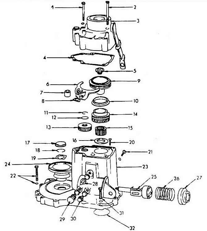
Gearbox housing and shift shaft
1 - screw, 25 Nm
2 - screw, 25 Nm
3 - gearbox housing cover
4 - seal
5 - screw, 150 Nm
6 - fifth gear engagement fork
7 - spacer sleeve
8 - locking plate
9 - fifth gear switch
10 - fifth gear synchronizing ring
11 - spring retaining ring
12 - thrust washer
13, 14 - fifth gear gears
15 - needle roller bearing
16 - thrust washer
17 - cover, subject to mandatory replacement
18 - spring retaining ring
19 - shaped washer
20 - screw, 15 Nm
21 - screw, 30 Nm
22 - screw, 25 Nm
23 - gearbox housing
24 - drive side flange
25 - switch shaft
26 - spring
27 - case
28 - Reverse switch
29 - fifth gear locking screw
30 - shift shaft locking screw
31 - screw, 25 Nm
32 - compensation washer
Disassembling the gearbox housing
The original article is available on the website VWmanual.ru
Loosen the transmission housing cover screws and remove the cover together with the seal.
Remove the locking plug for the shift shaft from the side of the gearbox housing.
Unscrew the reverse light switch.
Using a socket wrench, unscrew the shift shaft cap. Remove the spring, move the shift fork to the idle position and pull out the shift shaft. The forks must be moved to the idle position, otherwise the shaft cannot be pulled out. Unscrew the tachometer drive directly above the shift shaft locking plug.
Remove the Torx screw used to secure the reverse gear.
Remove the drive-side flange located in the clutch release area by pressing the middle plug out of the flange and removing the snap ring that holds the flange against the drive shaft.
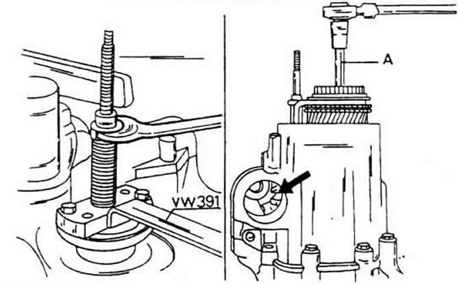
Disconnect with multi-tooth (polygonal) key (12 mm) screw from the inside of the shift sleeve. Since the screw is well tightened, such a push-on tip must be faceted so that it can be inserted into the head (on the right).
To stop the shaft, insert fifth gear (push the sliding sleeve down) and also insert reverse gear (push the power plug through the hole on the left down).
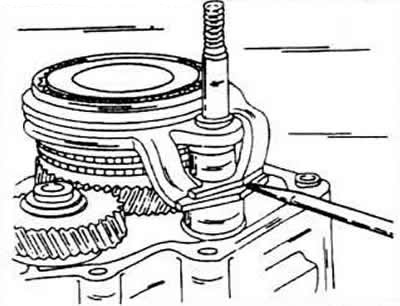
Use a screwdriver to press the locking plate downwards to secure the switching tube.
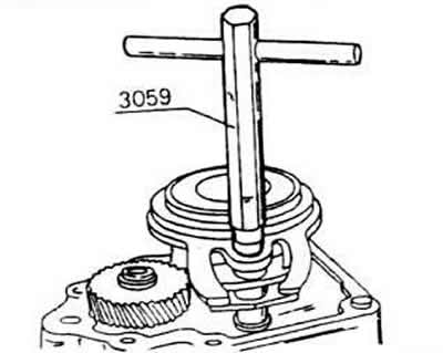
Using the special key 3059, unscrew the switching tube. Turn the key to the left. The switching bar does not need to be removed from the tube.
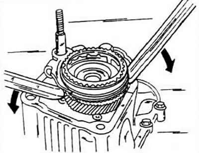
Pull out the shift sleeve together with the fifth gear pinion and the shift fork. To do this, place something under the lever assembly to press it down. before you can lift it straight up. Be careful not to damage the gearbox housing. There is a thrust washer under the shift sleeve.
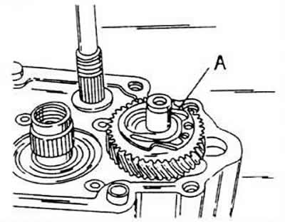
Remove the snap ring and thrust washer from the fifth gear. If disassembling a 2L engine case, hold the gear with a locking device.
Remove the fifth gear from the shaft using a two-arm removal tool.
Using a hexagon socket wrench (6 mm), unscrew the primary shaft bearing clamping plate. Four screws must be disconnected.
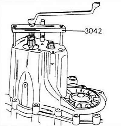
Disconnect the transmission case mounting screws and remove the case. If the case cannot be removed by tapping it with a plastic hammer, use the removal tool that is installed. The transmission case is now disassembled into two halves and further repair or adjustment operations can be carried out as described in the relevant sections.
If the gearbox housing, bearing housing and drive shaft are replaced, the thickness of the compensation washer on the bearing working ring must be re-determined.
Removal the primary shaft
With the gearbox housing removed, the primary shaft is removed as follows.
Remove the shift bar. It is held in a floating position by two springs (one in the gearbox housing, and the second in the bearing shield).
Remove the shift bar from the bearing shield and remove the complete set of shift forks from the side.
Disconnect the fourth gear snap ring from the top of the engine.
Remove the front shaft together with the fourth gear gear (this is the secondary shaft gear). Please note that the reverse gear is not engaged with the teeth of the other shafts. If necessary, move the reverse gear.
Disassembling the secondary shaft
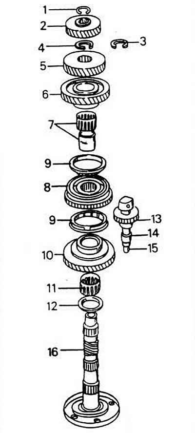
Secondary shaft installation diagram
1 - spring retaining ring
2 - fourth gear pinion
3 - additional spring retaining ring
4 - spring retaining ring
5 - third gear pinion
6 - second gear pinion
7 - needle roller bearing
8 - synchronizer, first-second gears
9 - synchronizing rings
10 - gear, first gear
11 - needle roller bearing
12 - thrust washer
13 - reverse gear
14 - thrust sleeve
15 - reverse shaft
16 - secondary shaft
The entire gear set must be removed before the secondary shaft can be removed from the bearing shield.
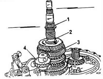
Remove the 4th gear secondary shaft snap ring and remove the gear. Make sure that the gear is placed with the flange facing up. In the 2-liter engine gearbox, the primary shaft diameter is larger, so the internal diameter of the gears is larger. In addition, a second snap ring 3 is used for fastening. In this case, the parts must be removed as follows:
Remove snap ring 1 before removing the third gear pinion.
Remove snap ring 2 from the third gear pinion.
Remove the synchronizing ring and needle roller bearing 3 from the third and second gear shaft.
Remove reverse gear 4 together with the shaft. If necessary, use a rubber hammer, and the reverse gear should be in the position shown in the figure, i.e. it should be adjacent to the stop.
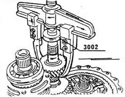
In other gearboxes, the pinion can be removed using a two-tooth puller if necessary.
There is a second snap ring under the pinion, which should also be removed. Its thickness may vary. The ring is used to adjust the axial clearance of the third gear pinion, which must be maintained. In this gearbox, the ring has a larger diameter.
Remove the third gear pinion. Immediately ensure that the pinion flange is facing downwards, i.e. towards the second gear pinion.
Remove the second gear pinion together with the needle roller bearing.
Remove the reverse shaft together with the reverse gear. In doing so, knock the shaft out of the bearing housing with a plastic hammer.
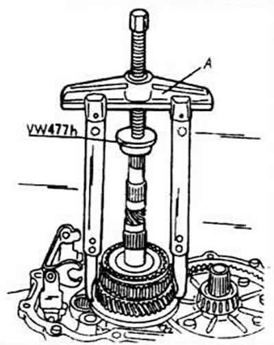
Using a two-pronged puller and a suitable pressure lug placed on the end of the shaft (arrow), remove the first gear pinion and the first-second synchronizer simultaneously.
Remove the first gear needle bearing and thrust washer. Note the position of the thrust washer.
Unscrew the gearbox bearing cover. Use four screws to secure it. Remove the cover.
Remove the shaft from the bearing housing.
Removal the differential
Remove the differential primary shaft flange in the same way as described for the gearbox housing. Lift the differential together with the main gear pinion. The primary and secondary shafts must be removed first.
The bevel satellite shaft is held in place by two extended flat bevel pinion rivets.
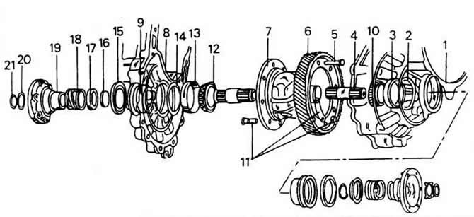
1 - bearing shield
2 - compensation washer S2
3 - bearing working ring
4 - drive shaft for flange
5 - rivet (only during production)
6 - flat bevel gear
7 - differential box
8 - gearbox housing
9 - tin sleeve
10 - tapered roller bearing
11 - screw and nut, 70 Nm
12 - tapered roller bearing
13 - bearing working ring
14 - compensation washer S1
15 - oil seal ring
16 - conical ring
17 - thrust ring
18 - compression spring
19 - drive side flange
20 - shaped washer
21 - spring retaining ring
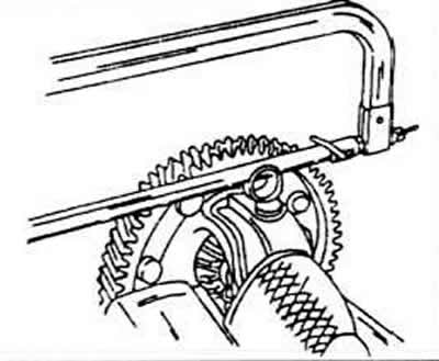
Cut both rivets to the same length relative to the differential axle and knock the axle out of the housing. Make sure that no sawdust gets into the differential bearing.
Remove the snap rings from the inside of the differential.
Remove the differential gears and remove the plastic carrier.
Using a two-arm removal tool, you can remove the differential bearings.
Disassembling the primary shaft
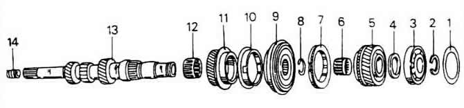
1 - compensation washer
2 - spring retaining ring
3 - ball bearing
4 - thrust washer
5 - fourth gear pinion
6 - needle roller bearing
7 - fourth gear synchronizing ring
8 - spring retaining ring
9 - synchronizer of third-fourth gear
10 - third gear synchronizing ring
11 - third gear pinion
12 - needle roller bearing
13 - primary shaft
14 - bushing
The primary shaft of the gearbox has a thickening in the areas of the fine-spline profile of the drive disk, oil seal ring and front needle roller bearing.
Press out ball bearing 3 under a press. To do this, insert the pressing plates of the press between the bearing and the fourth gear pinion.
Using a press, press out the 4th gear 5, but this time place the retaining plates under the gear.
Remove needle roller bearing 6.
Remove the spring retaining ring 8 used to secure the third-fourth gear synchronizer. Press out the synchronizer 9. The retaining plates are inserted under the third gear pinion.
Remove needle roller bearing 12.
Visitor comments