



| Nominal value | Inlet valve: | 0.15-0.25 mm |
| Exhaust valve: | 0.40-0.50 mm |
After repairing the cylinder head, the valve clearance must be adjusted with the engine cold.
| Nominal value | Inlet valve: | 0.15-0.25 mm |
| Exhaust valve: | 0.35-0.45 mm |
The valve clearance should be checked and, if necessary, adjusted every 15,000 km. It is carefully checked and, if necessary, adjusted after repair of the cylinder head (after 1000 km). Adjusting the clearance will only be successful if the valves are tightly sealed, there is no unacceptable clearance in the valve guides and the valves are not damaged at the stem ends.
If the clearance is too small, the valve timing changes, poor compression is observed, engine power decreases, and the engine runs unevenly. In extreme cases, the valves may become deformed, and the valves or their seats may burn out.
If the gap is too large, strong mechanical noises are observed, the timing changes, the engine produces little power due to insufficient filling of the cylinders, and the engine runs unevenly.
To adjust the clearance, there are special installation washers with a thickness of 3.00 to 4.25 mm. The thickness of the washer is etched on the bottom side. When installing, it is necessary to pay attention to the fact that this designation is facing down, i.e. towards the cup-shaped pusher.
Mounting washers and their numbers:
| Thickness, mm | Number | Thickness, mm | Number |
| 3,00 | 056 109 555 | 3,65 | 056 109 568 |
| 3,05 | 056 109 556 | 3,70 | 056 109 569 |
| 3,10 | 056 109 567 | 3,75 | 056 109 570 |
| 3,15 | 056 109 568 | 3,80 | 056 109 571 |
| 3,20 | 056 109 569 | 3,85 | 056 109 572 |
| 3,25 | 056 109 570 | 3,90 | 056 109 573 |
| 3,30 | 056 109 571 | 3,95 | 056 109 574 |
| 3,35 | 056 109 572 | 4,00 | 056 109 575 |
| 3,40 | 056 109 573 | 4,05 | 056 109 576 |
| 3,45 | 056 109 574 | 4,10 | 056 109 577 |
| 3,50 | 056 109 575 | 4,15 | 056 109 578 |
| 3,55 | 056 109 576 | 4,20 | 056 109 579 |
| 3,60 | 056 109 577 | 4,25 | 056 109 580 |
Washers installed earlier can be used in the future if they do not have mechanical damage.
Installation
Remove the air filter.
Remove the cylinder head cover, see. "Cylinder head".
Adjustment of the valve clearance is performed in the following sequence: 1-3-4-2 cylinder. The 1st cylinder is opposite the flywheel.
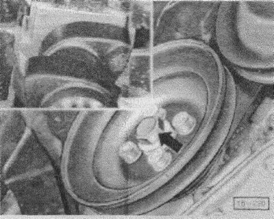
(15-220) Turn the crankshaft with a belt pulley using a socket wrench or with 4th gear engaged by pushing the car until the cam pair of the adjustable cylinder points upward. Then the cam pair will not lie on the installation washers.
Caution! Do not rotate the camshaft wheel by the fastening bolt, as this will subject the toothed belt to a high load. When the engine is rotated in the opposite direction by the crankshaft, for example when adjusting the valves, it may happen that the bolt fastening the toothed belt to the shaft breaks off.
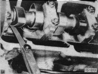
(15-013) Measure the valve clearance using a template.
Attention! Valve order from the engine end: 1st cylinder exhaust - intake; 2nd: outlet - inlet; 3rd: inlet - outlet; 4th: Inlet - Outlet. The template should fit back and forth between the cams and the mounting washer with difficulty.
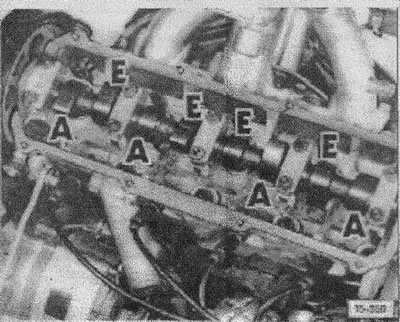
(15 - 358) pay attention to the sequence of the inlet and outlet valves, measure the valve clearances and record their value. A - outlet valve, E - inlet.
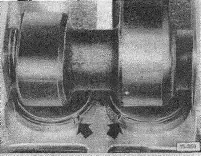
(15-359) Before applying the clamp, turn the cup-shaped plunger so that the grooves lie on the side of the suction pipe.
Attention! When adjusting the clearances, the piston should not be at the top dead center, otherwise, the valves will be pressed against the piston and destroyed. Therefore, turn the cardan shaft approximately 1/4 turn more.
Adjust the gap. For this purpose, workshops use special tools VW 546 and 10-208, which are supplied by various companies in a similar design. Without these tools, gap adjustment is impossible. Using a special clamp, press the cup-shaped pusher down. The mounting washer is pulled out with pliers.
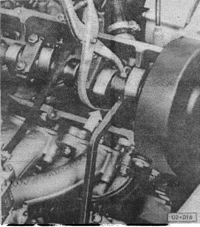
Attention! Since August 1982, clamp 2078 is required. There is a corresponding designation on the cylinder head cover.
(02-016) insert the required mounting washer.
Attention! The inscriptions must point downwards.
Remove the clamp and turn the camshaft further.
Adjust the valves of the 3rd cylinder, etc.
Note: As the mileage increases, the gap becomes smaller, which means that the previously installed washer is becoming too thick and needs to be replaced with another, thinner one.
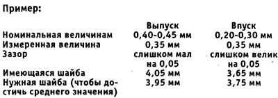
If the gap is within the tolerance, then there is no need to replace the washer. If the tolerance is not maintained, then when adjusting, you need to strive to achieve an average value, for example, 0.25 mm.
Apply new cover gaskets. Screw on cover, see. "Cylinder head".
Install the air filter.
Visitor comments