



Contents: Disassembling the head ↓ Checking the head ↓
Disassembling the head
- Unscrew the glow plugs.
- Remove the injector mounts. To remove the camshaft, begin by unscrewing the screws of the 1st and 4th bearing caps alternately and crosswise (number 1 indicates the front bearing). Then remove the caps of the 2nd and 3rd bearings
- Remove the camshaft.
- Remove the tappets together with the adjusting plates.
It is recommended to mark the tappet-head hole pairs accordingly, as this will make it easier to find the appropriate working clearance and adjust the valve clearance later.
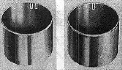
Figure 2.11. Designation of valve tappets. The designation must be made inside the parts.
- Use a special clamp to compress the valve spring, then remove the half-wedges and upper seats.
- Remove the outer and inner springs, as well as the lower spring seats. Using a special tool, remove the rings that seal the valve stems.
- Remove the valves from the guides. If they are to be installed again, it is recommended to mark them so that the corresponding guide can be found later.
Checking the head
After disassembling, the head must be cleaned. Check for distortions. A tolerance of 0.10 mm is acceptable. If this tolerance is not met, replace the head, as grinding of its connecting surface is not provided. If scratches are found at the level of the valve seats, repair of the head is permitted, provided that these scratches are no deeper than 0.50 mm.
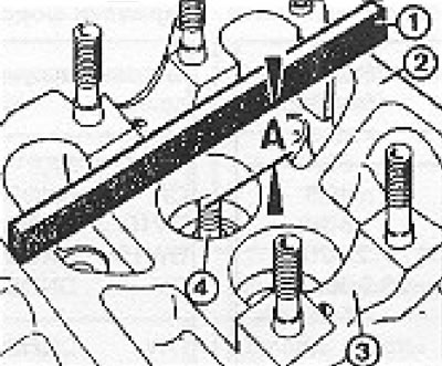
Figure 2.12. Calculation of the maximum permissible thickness of the ground layer of the seat (motors DV 1 G and DW 1 S): A - Inlet valve: 35.8 mm; exhaust 36.1 mm; 1 - Ruler; 2 - Upper surface of the head; 3 - Camshaft bearing; 4 - Valve stem.
Visitor comments