
English Русский
Български
Беларускі
Український
Српски
Hrvatski
Română
Polski
Slovenský
Magyar
  |  Articles  |  Sitemap  |  Contacts  |    |
Car maintenance Ford Car maintenance Hyundai Car maintenance Chevrolet Car maintenance BMW Car maintenance Audi Car maintenance Opel Car maintenance AvtoVAZ
VWmanual.ru


Main   Passat   Golf   Polo   Touareg   Tiguan   Sharan   Transporter   Others  
LT 28 (1975-1991) LT 2D (1996-2003) Beetle (1960-1986) Caddy 3 (2003-2010)

Adjusting valve clearances (VW Lt 28)

  • Main
  • Volkswagen
  • LT 28
  • Power unit
  • Diesel engines
  • Adjusting valve clearances
            0


Valve clearances can be adjusted with the head removed. The condition for this is that the head is firmly supported on the table and there is sufficient distance between the table top and the bottom surface of the head, which allows some of the valves to be lifted.

Attention!
  • The DV1G and DW1S engines have tappets with a hydraulic valve clearance reset device. These engines are identified by a sticker on the cylinder head cover.
  • If piston clearances are adjusted on the head mounted on the engine, do not rotate the crankshaft by pressing hard on the fan blades, as they may break. You should use a screwdriver.

Pushers (with hydraulic clearance adjustment)


Tappets should only be replaced as complete units and cannot be adjusted or repaired. When starting the engine, irregular noise produced by the valves is normal.

Examination


  • Maintain the increased speed until the engine reaches operating temperature.
  • Increase the rotation speed to 2500 rpm and hold it for approximately 2 minutes. Ensure that the tappets are not the source of the unusual noise. If so, proceed as follows:
    • Stop the engine.
    • Remove the head cover.
    • Turn the crankshaft gear in the direction of engine speed so that the cams working together with the tappet being tested are directed upward.
    • Use a wooden or plastic rod to press down on the plunger. If the idle stroke is found to be greater than 0.10 mm, the tappet must be replaced.
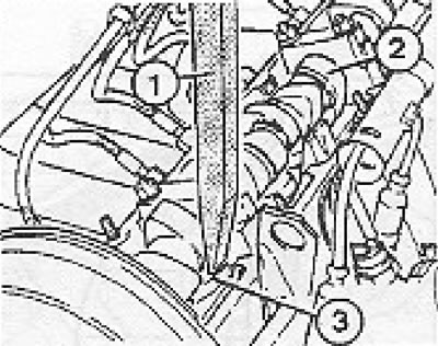
Figure 2.20. Checking the tappet with a hydraulic valve clearance release device (dV1G and DW1S…

Figure 2.20. Checking the tappet with a hydraulic valve clearance release device (dV1G and DW1S engines): 1 - Wooden or plastic rod; 2 - Camshaft; 3 - Pusher.


Caution! After replacing the tappet, do not start the engine for 30 minutes, as this may cause the piston to hit the valve. Under no circumstances should you attempt to rotate the engine crankshaft using the bolt on the front end of the camshaft, as this may cause damage to the timing belt.


Turn the camshaft (crankshaft if the head is installed on the engine) so that the cams of the cylinder being adjusted are facing upwards. Use a feeler gauge to check the clearance between the tappet adjusting plates and the cams. If the measured clearance is within tolerance, replacement of the tappet adjusting plates is not required.
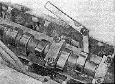
Figure 2.21. Checking valve clearance.

Figure 2.21. Checking valve clearance.


Valve clearance dimensions


For a warm engine (temperature above 35°C):
— inlet valve
0.20-0.30 mm
- exhaust valve0.40-0.50 mm.
For a cold engine:
— inlet valve
0.15-0.25 mm
- exhaust valve0.35-0.45 mm.

Example:
  • If the engine is warm and a 0.25 mm thick feeler gauge can be placed under the intake valve cam, then the clearance is adjusted very well.
  • If the thickness of the plate that can be placed under the intake valve cam is within 0.20-0.30 mm, there is no need to replace the tappet adjusting plate.
  • For example, if a 0.35 mm thick feeler gauge can be installed, then a 0.10 mm thick adjusting plate should be used. If a max. 0.15 mm, then the adjusting plate should be replaced with a thinner 0.10 mm one.

Caution! If the cylinder head is installed on the engine block, the piston corresponding to the valves whose clearance has been adjusted should not be at TDC. The cams should be facing upward. You need to turn the crankshaft a little to the right and left to close the valves.


Using special tool 2078, press the pusher down and remove the adjusting plate using pliers 12208.
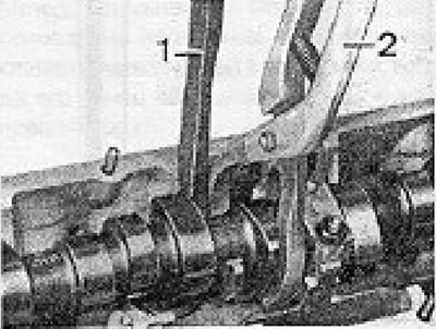
Figure 2.22 Method for replacing the valve clearance adjustment plates: 1 - Device 2078; 2 - Pliers…

Figure 2.22 Method for replacing the valve clearance adjustment plates: 1 - Device 2078; 2 - Pliers 12208.


The thickness of the plate is stamped on one of the surfaces. During installation, turn the surface with the marking in the direction of the tappet, i.e. in the opposite direction to the camshaft. The location of the intake and exhaust valves in the head should be determined (figure 2.23), because their working clearances are different.
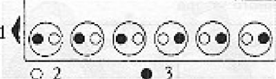
Figure 2.23. Location of valves in the head: 1 - Breeds; 2 - Intake; 3 - Graduation.

Figure 2.23. Location of valves in the head: 1 - Breeds; 2 - Intake; 3 - Graduation.


Attention! After performing head repair (for example, replacing gaskets, camshaft, etc.) be sure to adjust the valve clearance after 1000 km of vehicle mileage.


Table of valve clearance adjustment plates


Thickness (mm)N detailsThickness (mm)N details
3,00056 109 5553,65056 109 568
3,05056 109 5563,70056 109 569
3,10056 109 5573,75056 109 570
3,15056 109 5583,80056 109 571
3,20056 109 5593,85056 109 572
3,25056 109 5603,90056 109 573
3,30056 109 5613,95056 109 574
3,35056 109 5624,00056 109 575
3,40056 109 5634,05056 109 576
3,45056 109 5644,10056 109 577
3,50056 109 5654,15056 109 578
3,55056 109 5664,20056 109 579
3,50056 109 5674,25056 109 580

This article is available at russian, bulgarian, belarusian, ukrainian, serbian, croatian, romanian, polish, slovak, hungarian
The text has been checked: Kolesnikov Artem

Share information:

Previous articles
Assembling the head and installing the camshaft
Combustion chambers and valves
Valve seats — inspection, replacement
Cylinder head — disassembly, inspection
Cylinder head — removal
Engine installation
Next articles
Installing the head
Engine housing — general information
Crank-piston system
Distribution mechanism — installation
Lubrication system — oil pump
Cooling system


Similar articles from other manuals for VW cars:
Checking and adjusting clearances in the valve drive mechanism Passat B2 (1981-1988)
Adjusting valve clearances Golf 2 (1984-1993)
Removal and adjusting headrests Polo 3 (1995-2003)
Adjusting the valve timing Touareg 1 (2002-2006)
Removal and installation the throttle valve control unit and the… Tiguan 1 (2007-2015)
Adjusting the tension of the drive belt of engine units Sharan 1 (1995-2000)
Checking and adjusting the shut-off damper and the slow-down… Transporter T3 (1979-1992)
Link to this page in different formats


Visitor comments


No comments yet


How much will 31 + 30 =


Caddy 3 
  • General information
  • User manual
  • Daily care
  • Maintenance
  • Petrol engines 1.4 l
  • Engine repair
  • Cooling and lubrication system
  • Power and exhaust system
  • Petrol engines 1.6 l
  • Engine repair
  • Cooling and lubrication system
  • Power and exhaust system
  • Diesel engines
  • Engine repair
  • Cooling and lubrication system
  • Power and exhaust system
  • Transmission
  • Mechanical gearbox 0AH
  • Mechanical gearbox 0A4
  • Drive shafts
  • Chassis
  • Car suspension
  • Steering
  • Brake system
  • Body and wiring diagrams
  • Interior and exterior
  • Electrical circuits
Beetle 
  • General information
  • Maintenance
  • Power unit
  • Engine repair
  • Cooling and lubrication system
  • Supply system
  • Exhaust system
  • Transmission
  • Clutch
  • Car gearbox
  • Chassis
  • Front suspension
  • Rear suspension
  • Steering
  • Brake system
  • Wheels and tires
  • Body
  • Exterior
  • Electrical equipment
  • Equipment and devices
  • Power devices
  • Electrical circuits
LT 2D 
  • General information
  • User manual
  • Maintenance
  • Power unit
  • Petrol engines 2.3 l
  • Diesel engines 2.5 l
  • Diesel engines 2.8 l
  • Injection system (diesel 2.8 l)
  • Transmission
  • Clutch
  • Manual gearbox
  • Differential
  • Chassis
  • Car suspension
  • Steering system
  • Brake system
  • Body
  • Body elements
  • Heating system
  • Electrical equipment
  • Equipment and devices
  • Electrical circuits
LT 28 
  • General information
  • Maintenance
  • Power unit
  • Petrol engines 2.0L
  • Petrol engines 2.4L
  • Diesel engines
  • Cooling and heating
  • Fuel and exhaust system
  • Ignition system
  • Transmission
  • Clutch
  • Car gearbox
  • Cardan shaft
  • Rear axle
  • Chassis
  • Brake system
  • Car suspension
  • Steering system
  • Body
  • Body elements
  • Doors, locks and windows
  • Electrical equipment
  • Power devices
  • Equipment and devices
  • Electrical circuits
VWmanual.ru © 2016-2026 | Mobile version | News and articles | Sitemap: EN BG BY UA RS HR RO PL SK HU | Write message | Site search
Passat B2 • Passat B3 • Passat B4 • Passat B5 • Passat B6 • Golf 1, diesel • Golf 1, petrol • Golf 2, petrol • Golf 2 • Golf 3 • Golf 4 • Golf 5 • Polo 3 • Polo 4 • Touareg 1 • Tiguan 1 • Sharan 1 • Transporter T3 • Transporter T4 • LT 28 • LT 2D • Beetle • Caddy 3 •
Our website uses cookies to ensure functionality and convenience.