



Please note: The camshaft of the DV1G and DW1S engines differs from the camshafts of the other three engines. It can be quickly identified from the outside by the length of the rear gear neck (i.e. fuel pump drive gears). The camshaft is located at the top of the head. The installation method is described in paragraph 2.2.3 "Head".
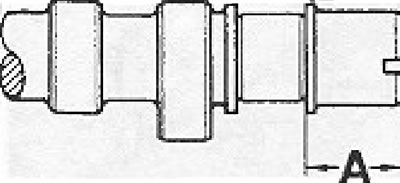
Figure 2.38. Differences in timing shafts. A - DV1G l DW1S engines: 20 mm, other engines: 25 mm,
Installation of the distribution mechanism
- Secure the inner metal cover of the timing drive.
- Install the gear on the crankshaft together with the vibration damper and toothed belt. Tighten the central bolt to 460 Nm.
Caution! When tightening the nut, if the head is installed on the engine, avoid rotating the crankshaft, as this can cause the piston to strike the valve.
- Make sure that the piston of the 1st cylinder is at TDC (mark on the flywheel opposite the corresponding mark). The cams corresponding to the 1st cylinder should be directed upwards, and the valves of the 6th cylinder should be diverging.
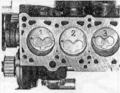
Figure 2.39. Installation method and numbering of pistons. The combustion chamber slots on the piston crowns should be on the left side of the engine.
- Install the special tool into the slot made on the rear end of the camshaft. If the workshop does not have the specified special device, you can use a 4.5 mm thick ruler.
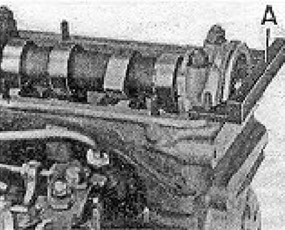
Figure 2.40. Installing the camshaft using a special tool. A - (4.5 mm thick).
Attention! A special device or ruler is used to install the camshaft when the piston of the first cylinder is at TDC in the compression stroke. Do not tighten the front camshaft nut if these tools are installed.
- Install the gear on the front end of the camshaft and install the timing belt at the same time. Loosely tighten the pinion bolt; the gear must turn on the camshaft.
- Install the alternator and vacuum pump V-belt.
- Install the air supply elements and fan.
- Using a special tool, adjust the tension of the timing belt by slightly moving the coolant pump; the value on the scale of the device should be between 12 and 13.
- Tighten the water pump mounting bolts.
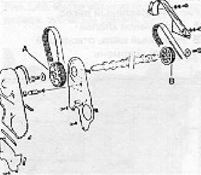
Figure 2.41. Camshaft. A - Front gear (mounting on a conical surface without a key), B - Identical rear fuel pump drive gear (mounting on a cylindrical surface without a key).
View the original on this portal: www.VWManual.ru
Attention! The timing belt tension value must be within the limits specified above. A belt that is too loose will cause vibration (shock) in the engine timing system, while a belt that is too tight can damage the coolant pump.
- Make sure that the piston of the 1st cylinder is at TDC (marks on the flywheel).
- Make sure that the special tool or ruler is located in the slot made on the rear end of the camshaft.
- Remove the specified control devices.
- Tighten the camshaft gear and tighten the bolts to the specified torque.
- Make sure that when the mark on the flywheel aligns with the corresponding mark, the special tool can be easily inserted into the recess at the rear end of the camshaft.
Visitor comments