



Crankshaft
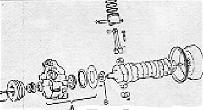
Figure 2.31. Crank-piston system. A - Oil pump; B - Slotted ring for oil pump drive
The crankshaft is supported by seven bearings. It requires three repair grindings of main journals and two grindings of connecting rod journals. Inserts corresponding to the dimensions of the journals after grinding are supplied as spare parts. Longitudinal fixation is provided by the intermediate bearing, and it is recommended to maintain the length of this bearing in particular (see subsection 2.1. "Technical specifications").
Self-priming and rechargeable motors are equipped with anti-vibrators that differ from each other. They are indicated by color dots as follows:
- Self-priming engines: black.
- Charging motors: green.
The first series of engines had front clutch shaft bearings (located at the rear of the crankshaft) 16 mm long. These bearings were later replaced by 20 mm long bearings.
Attention! It is recommended to use new type bearings during repairs.
- Clean engine lubrication lines thoroughly.
- Check the diametrical clearance of the shaft bearings.
These actions can be performed in two ways:
- Using an indicator clock with a micrometer.
- Method "plastigage".
- Install the bearing caps, observing the installation method and markings.
- Tighten the bolts to the specified torque.
- Measure the diameter of each bearing and the diameter of each journal.
- After this check, unscrew the bearing caps.
The lateral clearance is provided by the intermediate bearing shells.
- Lubricate the half-liners and journals of the crankshaft bearings with oil.
- Install the crankshaft by its two ends in the appropriate position.
- Install the bearing caps, observing the installation method and markings.
- Tighten the bearing cap bolts to the specified torque (see subsection 2.1. "Technical specifications").
- Using an indicator clock or a feeler gauge, check the crankshaft longitudinal clearance.
Rear bearing seal
The rear crankshaft bearing seal is provided by a ring in the cover. The cover is attached to the body together with the gasket, the cover bolts are tightened to the appropriate torque.
Connecting rods
The piston-connecting rod assembly can be easily knocked out of the engine from the top after ensuring that the carbon rim that could cause damage to the piston rings has been removed. The connecting rod heads are easy to separate; the head caps are marked by the manufacturer together with the connecting rods.
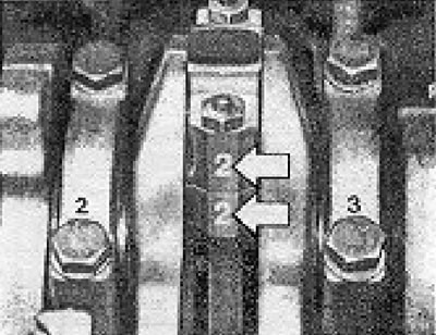
Figure 2.30. Connecting rod cap connection designation.
The connecting rods and connecting rod caps have special protrusions that must be directed towards the front of the engine during installation.
Attention! After grinding, the crankpins may have a max. two sizes. Accordingly, two repair inserts are provided. In addition, there are two types of connecting rod bolts.
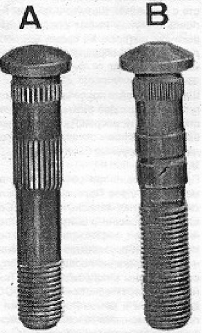
Figure 2.32. Differences in connecting rod bolts: A - Old type; B - New type.
Pistons
Three cylinder repair diameters are available. Pistons are supplied through the spare parts warehouse. The connection between the piston and the connecting rod is provided by a pin fixed with two spring rings. The values for piston extension from the housing are given in subsection 2.1. "Technical characteristics") and 2.2. "'Maintenance and repair" and relate to the head installation process. Depending on the piston extension, the appropriate cooking gasket should be selected.
Please note: The pistons of supercharged engines have cutouts in the lower part of the skirt for oil jets.
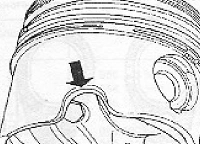
Figure 2.35. View of a piston detail of a rechargeable engine. The arrow shows a recess made in the bottom of the piston skirt to allow the oil jet to be inserted when the piston is at BDC
Assembling the piston with the connecting rod
- To assemble the piston and connecting rod, heat the piston to 60°C. At this temperature, the piston pin should rotate freely in the piston bushings.
- Install the spring ring into the piston groove.
- Warm up the piston.
- Place the piston in the connecting rod so that the cutout on the piston bottom ("trefi") is on the side of the connecting rod projections.
- Install the piston pin and the second spring ring.
- Install the piston rings, starting with the scraper ring and its expander. The slots of the scraper ring and expander should be on opposite sides, if possible, not on the end of the finger.
- Install the sealing ring with the "top" marking facing up, then the element ring.
- Place the cuts on all rings evenly around the piston perimeter without damaging the scraper ring.
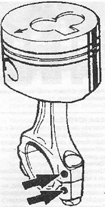
Figure 2.33. Designation for repairing a piston with a connecting rod. The "trefi" notch on the piston bottom should be on the side of the protrusion on the connecting rod (arrows).
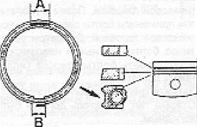
Figure 2.36. Location of rings in the piston. A - Section of the spacer spring; B - Section of scraper ring.
Installing the piston-connecting rod system
- Install the connecting rod-piston-piston ring assemblies in the cylinders so that the thickenings on the connecting rods are facing the front. The recess in the bottom of the "trefi" piston) must be located on the left side of the housing.
- Using a special cuff, compress the rings in the grooves and push the piston towards the crankshaft. Make sure that the crank pin is not at TDC during this operation.
- Place the half bearings into the connecting rod and into the connecting rod cap, then lubricate them.
- Install the connecting rod with the cover so that the marks are on the same side.
- Lubricate the contact surfaces of the connecting rod bolt nuts with oil and tighten to the specified torque.
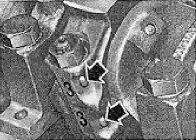
Figure 2.34. Designation of connecting rods. The arrows indicate the protrusions that should be facing towards the front of the engine
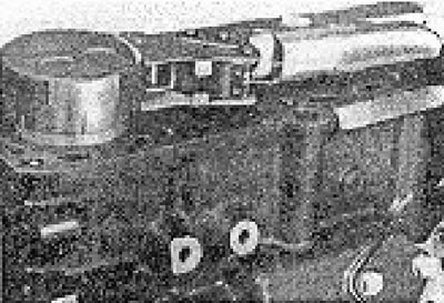
Figure 2.37. Installing the piston using the ring seal.
Visitor comments