
English Русский
Български
Беларускі
Український
Српски
Hrvatski
Română
Polski
Slovenský
Magyar
  |  Articles  |  Sitemap  |  Contacts  |    |
Car maintenance Ford Car maintenance Hyundai Car maintenance Chevrolet Car maintenance BMW Car maintenance Audi Car maintenance Opel Car maintenance AvtoVAZ
VWmanual.ru


Main   Passat   Golf   Polo   Touareg   Tiguan   Sharan   Transporter   Others  
LT 28 (1975-1991) LT 2D (1996-2003) Beetle (1960-1986) Caddy 3 (2003-2010)

Coolant pump — removal and installation (VW Lt 28)

  • Main
  • Volkswagen
  • LT 28
  • Power unit
  • Diesel engines
  • Coolant pump — removal and installation
            0


Contents: Removal the pump ↓ Installation ↓ Thermostat ↓

Removal the pump


Before removing the coolant pump, the cooling system must be drained.
  • Remove the vacuum pump V-belt, which can be done after removing the outer disc.
  • Remove the metal gear guard.

In a Volkswagen engine, the front timing belt must be removed. To avoid possible installation errors, it is recommended to set the engine to the injection start position in the 1st cylinder and to do this, align the fuel pump alignment marks in a single line. The mark on the flywheels must be positioned opposite the mark in the clutch housing (see drawing in p. 2.2.9 "Injection system").
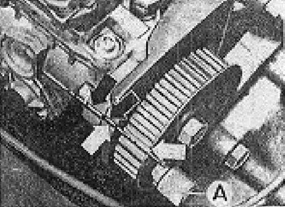
Figure 2.48. Fuel pump installation marks, timing belt removed.

Figure 2.48. Fuel pump installation marks, timing belt removed.

  • Lock the front camshaft gear to loosen the mounting bolt one turn.
  • Loosen the coolant pump mounting bolts to remove tension from the timing belt.
  • Using a puller or a metal apron, separate the front gear from the camshaft.
  • Remove the gear and timing belt, then the rear metal cover.

Please note: The designer did not provide spare parts for repairing the coolant pump. In case of leaks or gaps in the roller, the entire pump unit must be replaced.


Installation


  • Thoroughly clean the inside of the coolant pump housing. A circular ring ensures tightness between the crankcase and the pump. When the pump moves and the toothed belt is tensioned, the ring slips in the crankcase, and the resulting leakage can cause a leak.
  • Install the fluid pump in the crankcase without tightening the bolts.
  • Install the rear metal timing belt cover.
  • Install the gear with the toothed belt on the camshaft, but do not tighten the bolts. The gear must rotate on the camshaft.
  • Check if the crankshaft has turned; the mark on the flywheel should be opposite the mark on the clutch housing.
  • Make sure that the camshaft does not rotate; the marks on the fuel pump must be aligned.
  • Tighten the timing belt by turning the coolant pump and then tighten the bolts securing the pump. Using a special device, check the belt tension (see section 2.2.6 "Distribution system").
  • Using a special lever, lock the front camshaft gear and tighten the gear bolts to the appropriate torque.

[View the original on this portal: www.vwmanual.ru]


Important! If you are unsure of the camshaft position, we recommend checking its alignment using a 4.5 mm gauge.
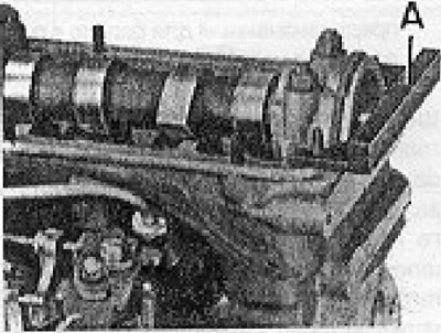

Figure 2.51. Checking the camshaft installation. A - Special device (4.5 mm thick)

Figure 2.51. Checking the camshaft installation. A - Special device (4.5 mm thick)


  • Check whether the fuel pump is always in the position marked on the flywheel in the TDC position. Otherwise, it is necessary to install the distribution after removing both gears of the distribution shaft (see point 2.2.6 "Distribution system").
  • Install the alternator and vacuum pump V-belt. Belt tension is achieved by installing more or fewer shims between the two discs.
  • Fill the system with coolant.


Attention! Coolant is a mixture of water and G10 antifreeze with anti-corrosion properties. This liquid prevents water from freezing, corrosion, retains limescale deposits and increases the boiling point of water. For proper engine operation, it is recommended to use this fluid all year round, even in tropical conditions.


Thermostat


The thermostat is located in the horizontal outlet of the coolant pump housing, the mark on the outer part should be facing up and out.

This article is available at russian, bulgarian, belarusian, ukrainian, serbian, croatian, romanian, polish, slovak, hungarian
The text has been checked: Kolesnikov Artem

Share information:

Previous articles
Cooling system
Lubrication system — oil pump
Distribution mechanism — installation
Crank-piston system
Engine housing — general information
Installing the head
Next articles
Injection system and fuel pump
Nozzle holders and nozzles
Glow plugs — general information
Turbocharger — general information


Similar articles from other manuals for VW cars:
Checking the additional coolant pump Passat B3 (1988-1993)
Coolant circulation pump Golf 3 (1991-1997)
Removal and installation the coolant pump (petrol engines) Polo 4 (2001-2009)
Draining and filling coolant (petrol engine) Touareg 1 (2002-2006)
Coolant run-off pump V51 Tiguan 1 (2007-2015)
Coolant circulation pump Sharan 1 (1995-2000)
Windshield Washer Water Pump — Checking and Replacing Transporter T4 (1990-2003)
Link to this page in different formats


Visitor comments


No comments yet


How much will 26 + 37 =


Caddy 3 
  • General information
  • User manual
  • Daily care
  • Maintenance
  • Petrol engines 1.4 l
  • Engine repair
  • Cooling and lubrication system
  • Power and exhaust system
  • Petrol engines 1.6 l
  • Engine repair
  • Cooling and lubrication system
  • Power and exhaust system
  • Diesel engines
  • Engine repair
  • Cooling and lubrication system
  • Power and exhaust system
  • Transmission
  • Mechanical gearbox 0AH
  • Mechanical gearbox 0A4
  • Drive shafts
  • Chassis
  • Car suspension
  • Steering
  • Brake system
  • Body and wiring diagrams
  • Interior and exterior
  • Electrical circuits
Beetle 
  • General information
  • Maintenance
  • Power unit
  • Engine repair
  • Cooling and lubrication system
  • Supply system
  • Exhaust system
  • Transmission
  • Clutch
  • Car gearbox
  • Chassis
  • Front suspension
  • Rear suspension
  • Steering
  • Brake system
  • Wheels and tires
  • Body
  • Exterior
  • Electrical equipment
  • Equipment and devices
  • Power devices
  • Electrical circuits
LT 2D 
  • General information
  • User manual
  • Maintenance
  • Power unit
  • Petrol engines 2.3 l
  • Diesel engines 2.5 l
  • Diesel engines 2.8 l
  • Injection system (diesel 2.8 l)
  • Transmission
  • Clutch
  • Manual gearbox
  • Differential
  • Chassis
  • Car suspension
  • Steering system
  • Brake system
  • Body
  • Body elements
  • Heating system
  • Electrical equipment
  • Equipment and devices
  • Electrical circuits
LT 28 
  • General information
  • Maintenance
  • Power unit
  • Petrol engines 2.0L
  • Petrol engines 2.4L
  • Diesel engines
  • Cooling and heating
  • Fuel and exhaust system
  • Ignition system
  • Transmission
  • Clutch
  • Car gearbox
  • Cardan shaft
  • Rear axle
  • Chassis
  • Brake system
  • Car suspension
  • Steering system
  • Body
  • Body elements
  • Doors, locks and windows
  • Electrical equipment
  • Power devices
  • Equipment and devices
  • Electrical circuits
VWmanual.ru © 2016-2026 | Mobile version | News and articles | Sitemap: EN BG BY UA RS HR RO PL SK HU | Write message | Site search
Passat B2 • Passat B3 • Passat B4 • Passat B5 • Passat B6 • Golf 1, diesel • Golf 1, petrol • Golf 2, petrol • Golf 2 • Golf 3 • Golf 4 • Golf 5 • Polo 3 • Polo 4 • Touareg 1 • Tiguan 1 • Sharan 1 • Transporter T3 • Transporter T4 • LT 28 • LT 2D • Beetle • Caddy 3 •
Our website uses cookies to ensure functionality and convenience.