



Contents: Injection system ↓ Fuel pump ↓
Injection system
The engine described is equipped with a BOSCH EP/NE fuel distribution pump, located at the rear on the left side of the engine and operating from the camshaft via a toothed belt.
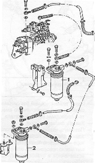
Figure 2.49. Fuel pump supply system: 1 - Fuel filter; 2 - Water settling tank.
Fuel pump
Removal the pump
- Remove the metal protection of the pump toothed belt.
- Remove the cooling system equalizer block and place it along with the wires on the side of the engine.
- Remove the air filter.
- Turn the crankshaft (do not use fan blades for this purpose - they can be damaged! The crankshaft can be turned with a screwdriver inserted into the clutch housing hole or with the vacuum pump mounting bolt) so that the piston of the 1st cylinder is in the injection position. The marks on the pump housing must correspond to the marks on the gear, and the mark on the flywheel must be opposite the marks on the clutch housing).
- Lock the fuel pump gear with a rod (diameter 15.5 mm and length 70 mm), which must be placed in the hole of the gear cover and in the mount. Seize the fuel pump drive gear (i.e. the rear camshaft gear).
- Remove the bolts and remove the gear and timing belt. Despite the corresponding slots, the gear is not fixed in the groove.
- Turn the fuel pump gear nut one turn.
- Remove the pin locking the gear.
- Using a special claw puller (with a hook in the holes of the gear protection) separate the gear from the pump shaft by lightly tapping the middle bolt of the puller.
- Remove the puller, unscrew the nut and then remove the gear.
- Disconnect the supply and return wires from the pump.
- Disconnect the acceleration and engine immobilizer controls.
- Unscrew the bolts securing the pump to the console. To loosen the bolts between the pump and the engine housing, use a 220mm long wrench designed for hexagonal socket head bolts.
Please note! The rear camshaft and fuel pump gears are identical and have the same designation in the spare parts catalog. The fuel pump gear is mounted with a key, while the camshaft gear is mounted without a key. Both of these gears are installed differently. The camshaft gear is installed so that the disc faces the front of the engine, while the pump gear disc should face the gearbox.
Pump installation and assembly
Install the pump on the console without tightening the bolts so that the marks on the pump body and on the engine crankcase correspond to each other.
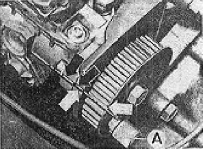
Figure 2.48. Fuel pump installation marks, timing belt removed.
- Install the pump drive gear together with the mounting key. The gear disc should be at the back.
- Seize the gear and tighten the nut to the appropriate torque.
- Check if the camshaft is installed correctly (see Figure 2.51).
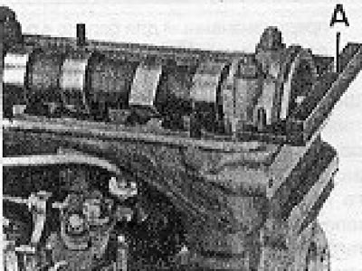
Figure 2.51. Checking the camshaft installation. A - Special device (4.5 mm thick)
- Install the gear and timing belt at the rear end of the camshaft. The gear must be installed so that the disc is facing the front of the engine. The bolt should not be tightened so that the gear can rotate freely.
- Adjust the belt tension by moving the pump console down or up.
- Check the belt tension using a special device (reading between 12 and 13 on the scale).
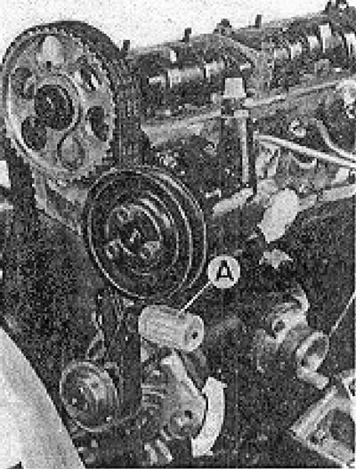
Figure 2.42. Timing belt line on the front of the engine. Measured with a special device A - the value on the scale should be 12-13
- Make sure that the fuel pump gear is at the TDC mark.
- Install the fuel pump gear using the pin.
- Lock the camshaft gear and tighten the bolt to the specified torque.
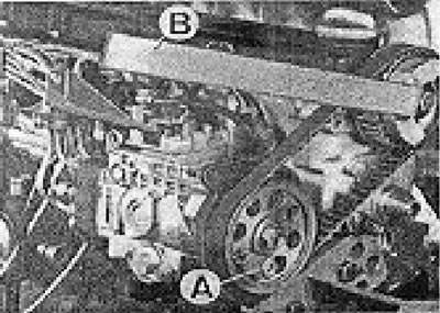
Figure 2.55. Locking the rear camshaft gear to tighten the nut to the appropriate torque: A - Fuel pump gear locking pin; B - Lever that presses the camshaft gear.
- Remove the pin from the fuel pump gear.
Checking the installation
- Unscrew the central bolt on the fuel pump dome.
- In place of the central bolt, install a special fitting equipped with a clock-type sensor, ensuring a depth of 2.5 mm.
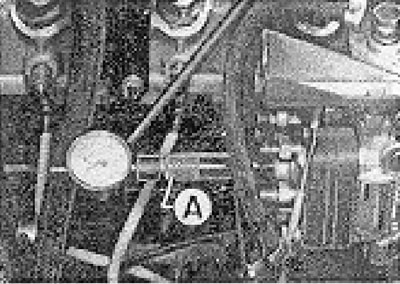
Figure 2.54. Checking the pump installation using a dial gauge. A - Sensor console.
- Turn the crankshaft (inserting a screwdriver into the hole in the clutch housing) in the direction opposite to the direction of engine rotation until the sensor arrow stops moving.
- Adjust the sensor to "0" with an initial load of 1 mm.
- Turn the crankshaft in the direction corresponding to the direction of engine speed until the mark on the flywheel matches the mark on the clutch housing. The gauge needle should show a pitch of 0.97 mm.
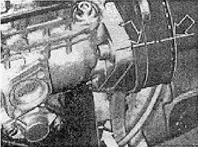
Figure 2.52. Fuel pump installation locations.
- Otherwise, you need to unscrew the fuel pump mounting bolts and get the appropriate step by turning the pump. Then you need to remove the sensor and its console and screw in the central bolt.
- Connect the high pressure wires, supply and return. The return wire hollow bolt has an "out" mark on the 6 walls.
- Connect the acceleration and engine lock controls.
Visitor comments