



Attach the stand with the indicator to the clutch housing (Fig. 4-34) and install the indicator leg on the end of the secondary shaft.
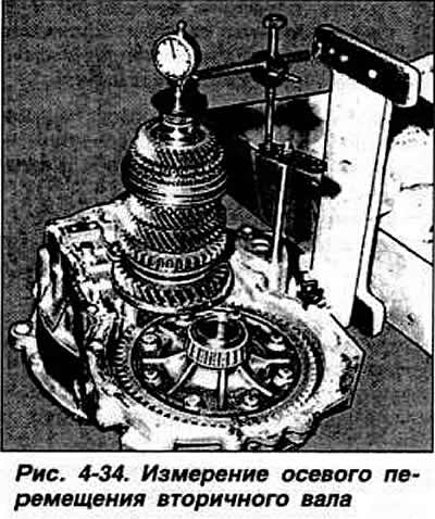
By moving the secondary shaft up and down in the axial direction and without turning it, mark the axial movement "X" of the secondary shaft on the indicator.
Calculate the required thickness "T" of the adjusting ring using the formula: T = 0.65 + 0.20 + X, where 0.20 mm is the value of the required preliminary load of the bearing.
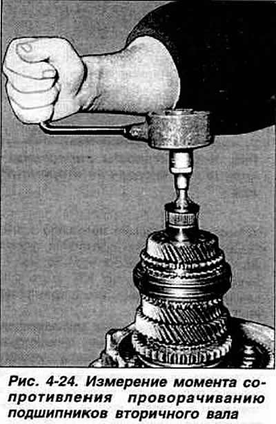
Install an adjusting ring of the thickness found in this way under the outer ring of the bearing, install the secondary shaft with bearings, having previously lubricated them with oil, and check the moment of resistance to rotation of the secondary shaft bearings (Fig. 4-24), which should be 0.3 kgf·m for worn-in bearings, and 1.3-1.8 kgf·m for new bearings.
Visitor comments