
Using a puller or press, press the tapered roller bearing inner races off the differential case.
With a drill with a diameter of 12 mm, drill out the heads of the rivets securing the driven gear of the final drive from the milled side of the gear and knock out the rivets.
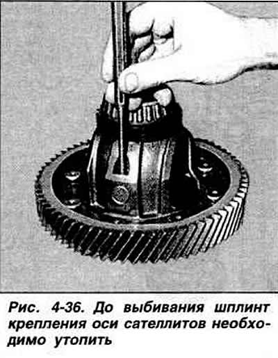
Using a punch, press the spring cotter pin for fastening the axis of the satellites into the axis (pic. 4-36) and press out the axis of the satellites. Knock out the spring cotter pin from the axis of the satellites. Remove side gears, pinion gears and thrust washers. Using a press, compress the final drive gear.
To assemble the differential, heat the final drive gear and press the gear onto the differential case. centering it with two bolts, wrap and tighten the special bolts for fastening the driven gear of the final drive with gasket plates.
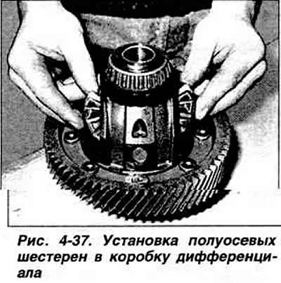
Install the thrust washers, lubricating them with gear oil, install the satellites, press in the axis of the satellites and install the spring cotter pin of the axle. pressing it flush with the surface of the differential box. Install side gears in differential box (pic. 4-37), then rotate them into place. Press the roller bearing inner races onto the differential case with a press.
Adjust differential bearing preload as follows.
Press the outer races of the differential bearings into the sockets of the clutch housing and gearbox housing.
Note. The inner and outer rings of the bearings are matched in pairs, so they cannot be separated.
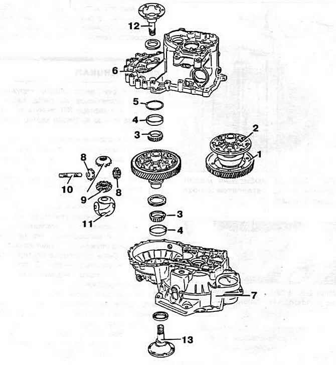
Pic. 4-35. Differential details:
1 - driven gear of the main gear;
2 - differential box;
3 - tapered roller bearing;
4 - the outer ring of the bearing;
5 — an adjusting ring of the bearing;
6 - gearbox housing;
7 - clutch housing;
8 - satellites;
9 - side gears;
10 - axis of the satellites;
11 - support clip;
12, 13 - differential output shaft.
Visitor comments