



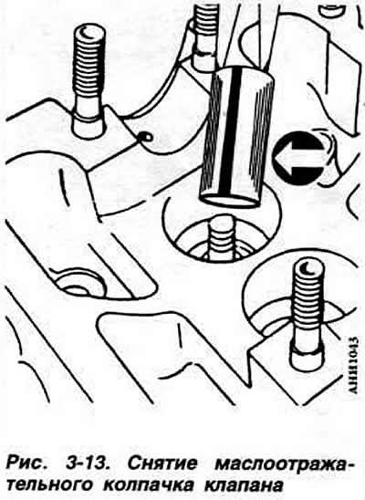
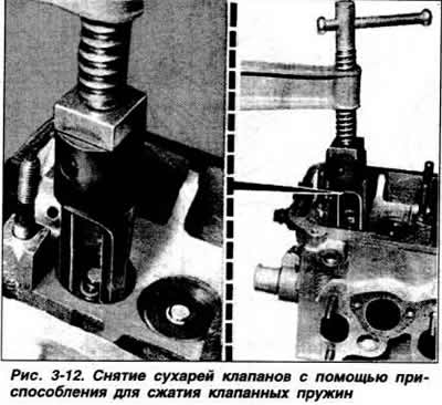
Remove the hydraulic valve tappets. Using the VW 20 37 valve spring compressor, remove the cotters, valve springs, plates and spring support washers. Remove the valve stem seals (Fig. 3-13). Remove the valves.
To check the technical condition of the cylinder head, wash the cylinder head parts with gasoline or trichloroethylene. Check the degree of wear of the valve guides. To do this, insert a new valve into the guide so that the end of the valve stem is flush with the edge of the guide, and measure the gap between the guide and the valve stem using the VW 387 device with an indicator. If the gap between the guide and the stem of the intake or exhaust valve exceeds 1.3 mm, replace the guides. Valve guides are supplied separately from the cylinder head as spare parts. Check the flatness of the mating surface of the cylinder head using a straightedge and a set of feeler gauges or on a surface plate.
If a non-flatness of more than 0.1 mm is detected on the mating surface, replace the cylinder head. The cylinder head cannot be ground. Check the condition of the valve seats and, if necessary, grind them as indicated below. Using a device with a VW 387 indicator, measure the gap between the guide sleeve and the valve stem.
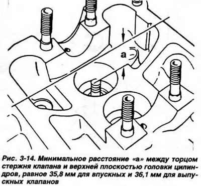
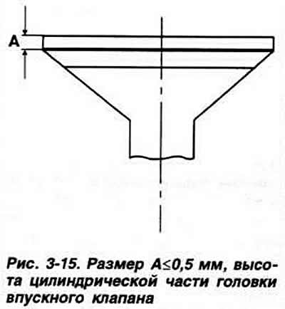
Grinding of valve seats and valve heads is performed using special tools. It is best to use a set of "Neway" tools. When grinding, observe the specified dimensions of the valve seats. Control the thickness of the metal being removed. If the maximum permissible grinding depth is exceeded, replace the cylinder head. In case of grinding of valve seats, in order to ensure normal operation of the hydraulic valve tappets, it is necessary to maintain a minimum distance "a" (Fig. 3-14) between the end of the valve stem and the upper plane of the cylinder head. If necessary, grind the working chamfers of the inlet valves, without going beyond the maximum dimensions. Exhaust valves are not subject to grinding. Only lapping them is allowed. When grinding the inlet valves, observe the dimension "A" (Fig. 3-15).
Check the valve head edge height. Grind the valves in their seats. Check the valves for leaks. After grinding and grinding the valves and seats, thoroughly clean the cylinder head.
The cylinder head is assembled in the reverse order of disassembly. Before assembly, thoroughly clean the cylinder head and all previously removed parts. Check the degree of wear of the camshaft, the radial runout of the middle journal of the shaft relative to the outer ones, the gap between the journals of the shaft and the bearing holes and the axial movement of the shaft. In case of replacement of valve guide bushings, lubricate the new bushings with oil and press them into the holes of the cold cylinder head from the camshaft side. The pressing force should not exceed 1 tf.
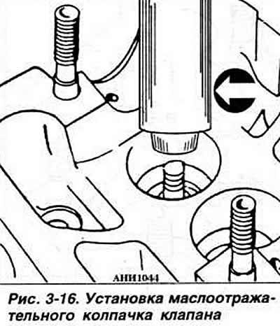
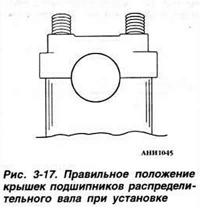
Install the valves. Lubricate the valve stems with engine oil, put the valve stem seals on them and press them in using the VW 10 204 tool (Fig. 3-16). Install the valve spring support washers. Install the valve springs and upper spring plates. Install the crackers using the VW 2037 tool for compressing the valve springs. Install the hydraulic valve tappets, having previously lubricated their bearing surfaces with engine oil. Install the camshaft in the cylinder head bearings, having lubricated the shaft journals and bearings with engine oil. Install bearing caps No.2 and 4 of the camshaft, paying attention to the correct position of the caps relative to the bearing bore axis (Fig. 3-17), and alternately tighten the cap fastening nuts crosswise to a torque of 2.0 kgf·m. Install bearing caps No.1, 5 and 3 and tighten the mounting nuts to the specified torque.
Visitor comments