
Interrogation of the storage device of malfunctions of the injection system
This operation can be performed using an LED probe.
In this case, the following order of operations must be strictly observed:
- interrogate the storage device;
- fix the problem found:
- erase information in the storage device. because the next survey can only be done by first eliminating the identified malfunction and deleting its code in the memory device;
- make the next interrogation of the storage device;
- if the malfunction is not detected, make a test drive in the car for at least 10 minutes and interrogate the memory device again.
Interrogation of the storage device of malfunctions of system of injection is made as follows.
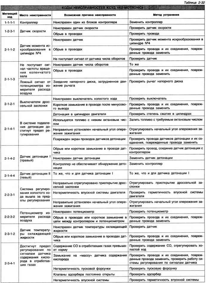
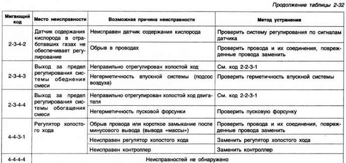
Move up the cover of the gear lever to access the terminals of the diagnostic block. Connect the wires of the LED probe to the wires of the black and blue terminals located at the top of the block. Connect two test leads to black and brown (or white) terminals located at the bottom of the diagnostic block, without connecting these wires to each other. Turn on the ignition. Connect the free ends of the test leads for 4 s, then disconnect them. In this case, the probe LED should blink. Determine the fault code by the number of flashes of the control lamp (table 2-32).
Erasing information in the fault memory
Connect the free ends of the test wires attached to the lower terminals of the diagnostic block, then disconnect them. In this case, the control LED should light up.
Reconnect the ends of the test wire for 4 s. The probe LED should show the code «4-4-4-4». it indicates that. that the previous DTC has been cleared.
Checking electrical circuits
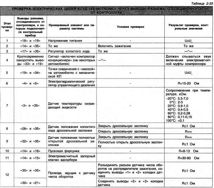
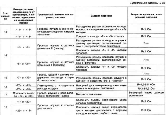
To check the electrical circuits of the KCM, disconnect the controller connector and use a tester to measure the resistance and voltage values at the terminals of the controller block. If these values deviate from the norm, first of all, check the corresponding electrical circuit, and then the KSUD element.
UOZ control subsystem
The UOZ KSUD control subsystem is a fully electronic ignition system. The controller calculates the optimal ignition timing depending on the engine operating conditions (speed, engine load and battery voltage). The ignition advance angle control subsystem generates appropriate control pulses to interrupt and resume the through current in the primary winding of the ignition coil.
The high voltage current that is induced in the secondary winding of the ignition coil during the break in the primary circuit is given through the distributor to the spark plugs. The distributor performs only the function of distributing high voltage current to the candles; the Hall sensor built into it provides information to the controller about the engine speed. The structure of the subsystem of the management of the UOZ includes:
- controller.
- ignition distributor with built-in Hall sensor;
- sparking torque sensor in cylinder No. 4;
- two knock sensors;
- ignition block;
- spark plug.
The ignition distributor with integrated Hall sensor is driven by the intake camshaft. Brand and catalog number:
- cars produced before March 1990: Bosch 051 905 205А;
- production vehicles from April 1990: Bosch 051 905 205V.
Adjusting ignition timing up to TDC at idle: 5-7°,
The resistance of the primary winding of the ignition coil at 20UC is 0.6-0.8 ohms. The resistance of the secondary winding at 20°C is 6.5-8.5 kOhm.
Brand and type of spark plugs: Bosch F6 DTC; Champion С6 BYC; Vegi 14F 6DTU. The gap between the electrodes is 0.7-0.9 mm.
Visitor comments