
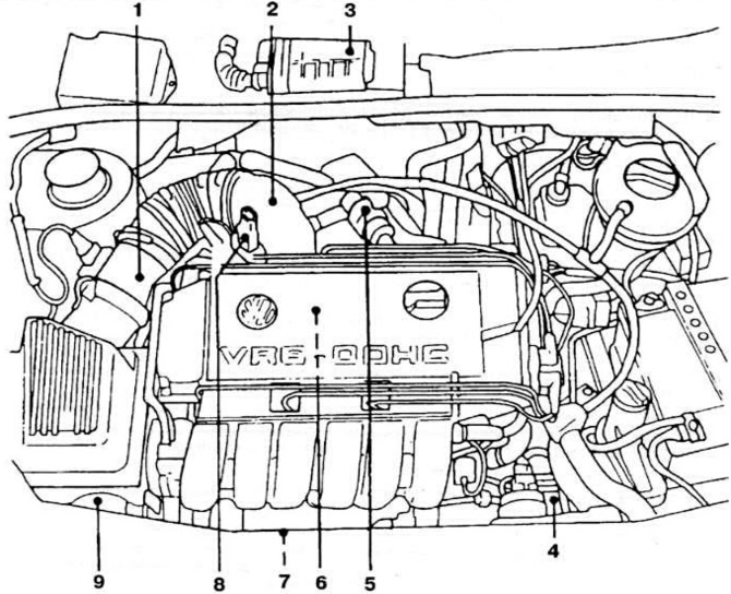
Pic. 15. Placement of elements of the fuel injection control subsystem KSUD «Motronic» by car «Passat 2,8 VR6»: 1 - mass air flow meter; 2 - throttle body; 3 - controller; 4 - intake air temperature sensor; 5 - idle speed regulator; 6 - nozzle; 7 - oxygen content sensor in exhaust gases; 8 - throttle position sensor; 9 - adsorber solenoid valve.
Before checking engine idling, perform the following operations:
- warm up the engine to an oil temperature of at least 80°C;
- check the correct adjustment of the gap between the electrodes of the spark plugs and the setting of the ignition timing;
- make sure that the air filter element is in good condition;
- turn off all auxiliary electrical equipment and air conditioning;
- make sure the exhaust system is tight.
Connect a control tachometer according to the operating instructions, start the engine and check the idle speed of the crankshaft, which should be within 650-750 rpm.
The idle speed of the crankshaft is automatically adjusted by the idle speed controller according to the signals of the controller and is not subject to manual adjustment.
Connect the gas analyzer according to the operating instructions and check the CO content in the exhaust gases, which should be within 0.3-1.2%.
The CO content in the exhaust gases is automatically adjusted by the controller based on the signals from the oxygen content sensor in the exhaust gases and is not subject to manual adjustment.
NOTE: Open throttle is set at the factory and cannot be adjusted in service.
Checking the fuel pressure in the system
Self-diagnosis code: 2-4-1-3.
Switch off the ignition.
Connect a pressure gauge to the measuring pipe of the system (pic. 12).
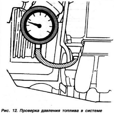
Start the engine at idle and check the regulated fuel pressure, which should be about 3.5 kgf/cm2. Disconnect the vacuum hose from the fuel pressure regulator and check the fuel pressure in the system using the pressure gauge, which should be about 4.0 kgf / cm2.
Connect the vacuum hose to the fuel pressure regulator. Turn off the ignition and after 10 minutes check the residual fuel pressure, which must be at least 2.5 kgf / cm2.
Throttle position sensor test
Self-diagnosis code: 2-2-1-2.
Switch off the ignition.
Disconnect the throttle position sensor connector, connect an ohmmeter to the terminals «1» and «2 «sensor pads (pic. 13) and check the readings of the ohmmeter, which should be in the range of 1.13-1.15 kOhm.
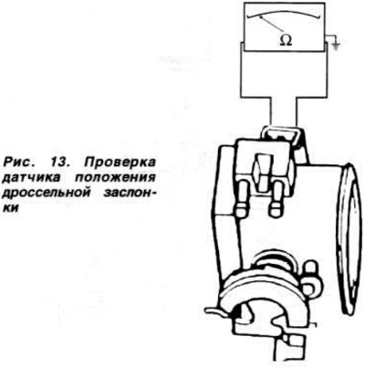
Slowly open throttle. In this case, the resistance on the ohmmeter should gradually increase.
Connect an ohmmeter to the leads «2» and «3» sensor pads and check its readings, which should be in the range of 2.68-2.72 kOhm.
Slowly open throttle. In this case, the resistance on the ohmmeter should gradually decrease.
Connect an ohmmeter to the leads «1» and «3» sensor pads and check its readings, which should be in the range of 1.98-2.02 kOhm.
Checking the coolant temperature sensor
Self-diagnosis code: 2-3-1-2.
Switch off the ignition.
Disconnect the blue coolant temperature sensor connector.
Remove the sensor from the engine and immerse it in a container of coolant.
Connect an ohmmeter to the sensor leads (pic. 14) and check the resistance of the sensor, which at a coolant temperature of 20°C should be 2.5 kOhm; at 40°C - 1.25; at 60°C - 0.6 and at 80°C - 0.325 kOhm.
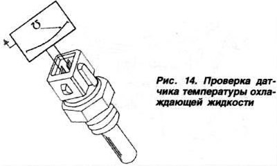
The coolant temperature sensor can be checked without removing it from the engine.
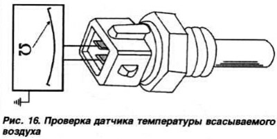
Checking the intake air temperature sensor
Switch off the ignition.
Disconnect the intake air temperature sensor connector and connect an ohmmeter to the sensor leads (pic. 16). Measure the resistance of the sensor, which at an ambient temperature of 10°C should be 3.5 kOhm; at 20°C - 2.5; at 40°C - 1.25; at 60°C - 0.6 and at 80°C - 0.325 kOhm.
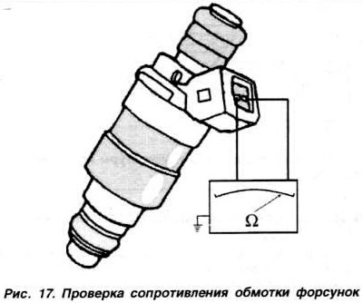
Checking the resistance of the injector windings
Switch off the ignition.
Disconnect the injector connector, connect an ohmmeter to its terminals (pic. 17) and check its readings, which should be in the range of 15.0-21.4 ohms.
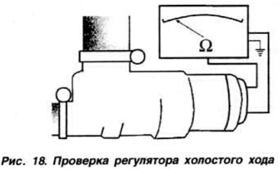
Checking the idle speed controller
Switch off the ignition.
Disconnect the idle speed controller connector, connect an ohmmeter to its terminals (pic. 18) and check its readings, which should be within 10-20 ohms.
Checking and adjusting the throttle damper
Open the throttle valve, then close it until it touches the pusher 2 (pic. 19) roller 3.
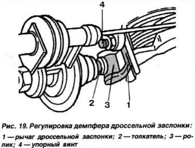
In this position, use a drill with a diameter of 3 mm to check the gap between the stop screw 4 and the lever 1.
If it is necessary to adjust the gap, clamp the drill between the screw and the roller, loosen the stop screw locknut and adjust the position of the damper so that the pusher 2 only slightly touches the roller 3.
Tighten the stop screw locknut.
Self-diagnosis
System self-diagnosis is performed as indicated in subsection «Self-diagnosis» for KSUD «KE-Motronic», described in section «16-valve engines», with the help of the controller, in the memory device of which fault codes are recorded. readable with appropriate hardware Before proceeding to interrogate the ROM. make sure fuses No. 18 and No. 21 are intact.
Visitor comments