



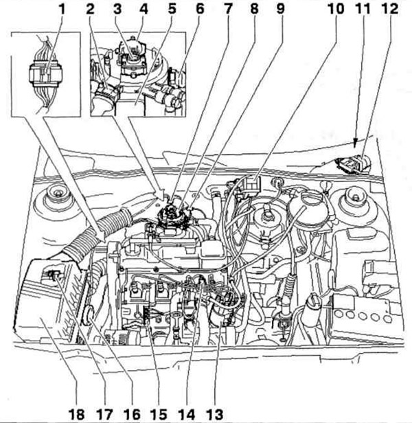
Fig. 5.43 a. Location of fuel injection and ignition system components:
1 - 4-pin oxygen sensor wiring connector; 2 - Wiring connector for injector and intake air temperature sensor; 3 - Fuel pressure regulator; 4 - Nozzle with inlet air temperature sensor; 5 - Throttle potentiometer with idle switch; 6 - Throttle potentiometer; 7 - Inlet air heating temperature regulator; 8 - Throttle body; 9 - Wiring connector for incoming air heating; 10 - Ignition coil; 11 - Intake manifold heater relay; 12 - Engine control unit; 13 - Ignition distributor with Hall sensor; 14 - Coolant temperature sensor; 15-Connection to "ground"; 16 - Vacuum unit for heating incoming air; 17 - Solenoid valve 1 activated carbon filter; 19 - Air filter.
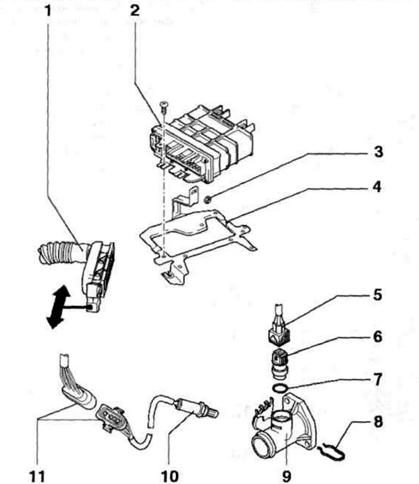
Fig. 5.43 b. Location of fuel injection and ignition system components:
1 - Engine control unit wiring connector; 2 - Engine control unit; 3 - Nut; 4 - Retainer; 5 - 4-pin coolant temperature sensor wiring connector; 6 - Coolant temperature sensor; 7 - Sealing ring; 8 - Retaining ring; 9 - Adapter; 10 - Oxygen sensor; 11 - 4-pin oxygen sensor wiring connector.
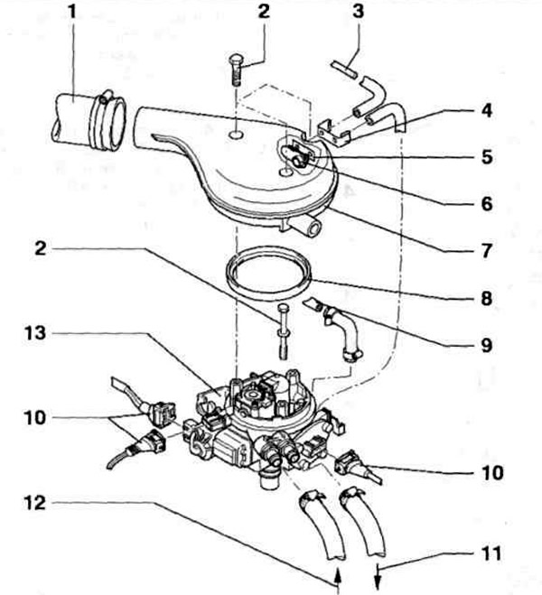
Fig. 5.43 c. Location of fuel injection and ignition system components:
1 - Air intake duct; 2 - Bolt; 3 - To the vacuum unit from the air filter; 4 - Retainer; 5 - Seal; 6 - Temperature regulator for heating the incoming air; 7 - Air filter; 8 - Seal; 9 - To the electromagnetic valve 1 of the activated carbon filter; 10 - Wiring connector; 11 - Fuel drain line; 12 - Fuel injection line; 13 - Throttle body.
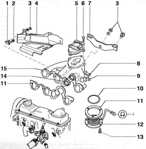
Fig. 5.43 d. Location of fuel injection and ignition system components:
1 - Bracket; 2, 6, 13 - Bolts; 3 - Nut; 4 - Support plate; 5 - Flange; 7 - Intake manifold support; 8 - To the cooling system pipe; 9 - To the brake booster; 10 - Sealing ring; II - Gasket; 12 - Inlet air heater; 14 - Seal; 15 - Intake manifold.
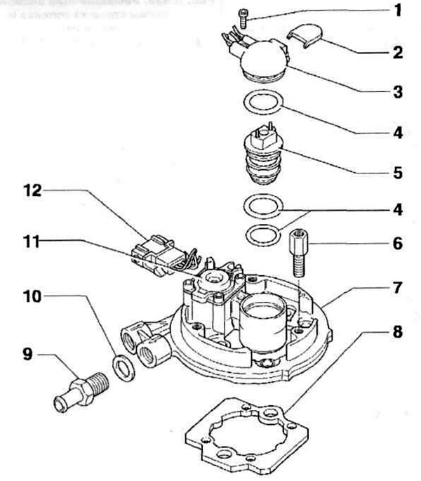
Fig. 5.43 d. Location of fuel injection and ignition system components:
1, 6 - Bolts; 2 - Protective cover; 3 - Nozzle retainer with inlet air temperature sensor; 4 - Sealing ring; 5 - Nozzle; 7 - Upper part of the throttle body; 8 - Gasket; 9 - Adapter; 10 - Seal; 11 - Fuel pressure regulator; 12 - Cork.
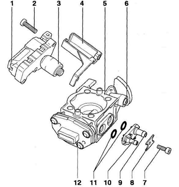
Fig. 5.43 e. Location of fuel injection and ignition system components:
1 - Throttle potentiometer with idle switch; 2, 7 - Bolts; 3 - Idle switch; 4 - Support bracket; 5 - Lower part of the throttle body; 6 - Limit screw; 8 - Retainer; 9, 10 - For vacuum tubes; 11 - Seals; 12 - Throttle potentiometer.
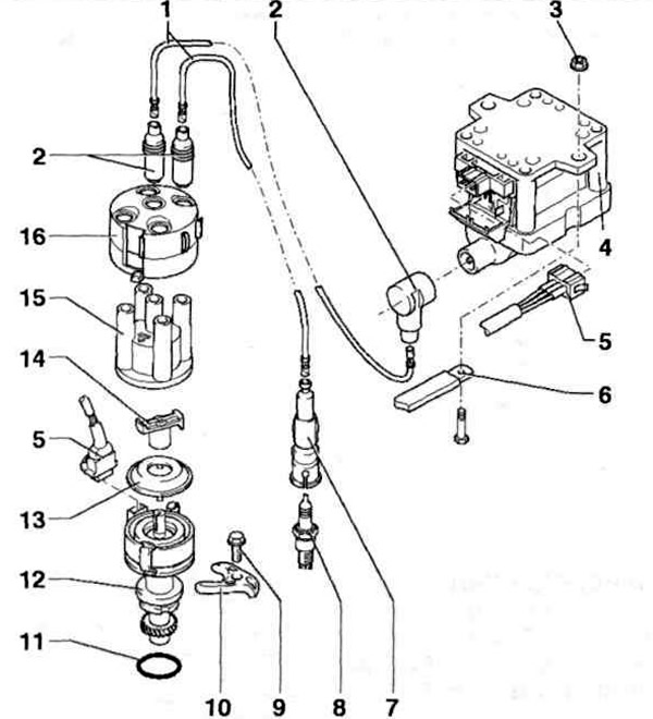
Fig. 5.43 g. Location of fuel injection and ignition system components:
1 - High voltage wires; 2 - Interference suppressor; 3 - Nut; 4 - Ignition coil; 5 - Wiring connector; 6 - "Ground" connection wire; 7 - Spark plug adapter; 8 - Spark plug; 9 - Bolt; 10 - Clamp; 11 - Sealing ring; 12 - Ignition distributor with Hall sensor; 13 - Lid; 14 - Distributor rotor; 15 - Distributor cover; 16 - Shielding cover.
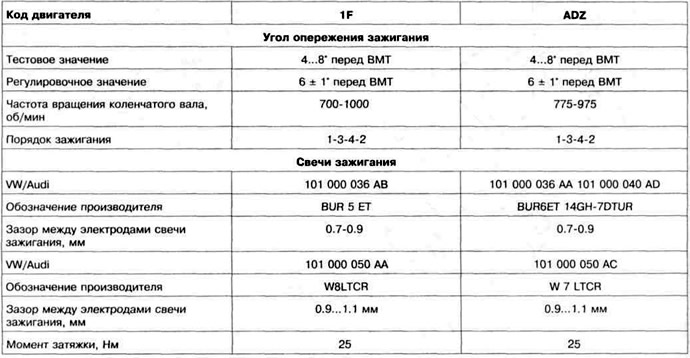
Table 5.2. Ignition system adjustment data and spark plug markings
Visitor comments