



- malfunctions that always occur;
- faults that are detected in no more than three seconds;
- malfunctions that occur more than five times per trip.
If the fault does not reoccur after the 19th engine start, it is automatically cleared from the memory. Faults can be read using the VAG 1551 or VAG 1552 fault code reader. Once the fault has been corrected, it must be cleared from the fault memory. If the ECM connector or power wires are disconnected from the battery, all data and contents of the fault memory are deleted. Self-diagnostic values are automatically updated after 10 trips. The mechanical limitation of the throttle potentiometer is determined by the control unit after a few seconds with the ignition on. The transmission version is determined when the engine is started and the speed exceeds 10 km/h. Self-diagnosis is not possible when the engine control unit checks the immobilizer signal. If the control unit does not receive a signal from the immobilizer, it is blocked. The engine does not start and the immobilizer warning light flashes for approximately 3 seconds after the ignition is turned on. Before you begin troubleshooting when the immobilizer warning light is flashing, interrogate the fault memory of the immobilizer control unit.
Data exchange between the engine control unit and the VAG 1551 fault code reader is carried out in the "LT Diagnostics" mode (LT Diagnosis). The engine control unit version is displayed when connecting a VAG 1551 fault code reader and selecting the "Engine Electronics" function. The layout of the Motronic injection and ignition control system components is shown in the figure 2.66. The available self-diagnostic functions are shown in Table 2.5.
Table 2.5. Available self-diagnostic functions
| Functions | The engine is not running, the ignition is on | The engine is idling | |
| 02 | Troubleshooting | Yes | Yes |
| 03 | Diagnostics of actuators | Yes | No |
| 04 | Basic installations | Yes1) | No |
| 05 | Clearing the fault memory | Yes | Yes |
| 06 | Completion of diagnostics | Yes | Yes |
| 07 | Control unit coding | No | No |
| 08 | Reading a block of measured values | Yes | Yes |
| 09 | Reading individual measured values | No | No |
| 10 | Setting up | No | No |
1)Should be carried out in the following cases: there is no voltage from the battery; when replacing the control unit, throttle control unit or engine.
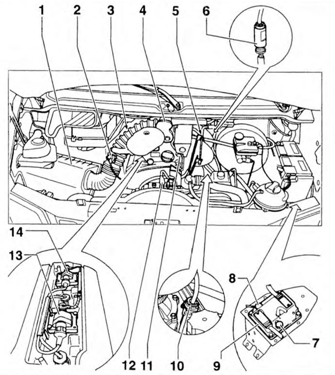
Figure 2.66. Location of the Motronic injection and ignition control system components: 1 - Air filter; 2 - Inlet air temperature sensor; 3 - Oxygen sensor; 4 - Throttle control unit; 5 - Crankshaft speed sensor; 6 - 4-pin connector for oxygen sensor and heater wiring: 7 - Resistor for control maps; 8 - Crankshaft speed sensor wiring connector; 9 - Motronic control unit; 10 - Throttle control unit wiring connector; 11 - Fuel distributor; 12 - Coolant temperature sensor; 13 - Transformer for 2 and 3 cylinders; 14 - Transformer for 1 and 4 cylinders
Visitor comments