




Fig. 2-50. Structural diagram of the SCV "Mono-Jetronic" "RP" engines:
1 - fuel pump;
2 - fuel tank;
3 - fine fuel filter;
4 — fuel pressure regulator;
5 - electromagnetic fuel injector;
6 — ECU;
7 — idle speed controller;
8 — throttle position sensor;
9 — intake manifold heater;
10 - coolant temperature sensor;
11 - exhaust gas oxygen sensor;
12 — ignition distributor sensor with built-in Hall sensor;
13 — switch;
14 — battery;
15 - ignition switch;
16 — relay for switching on the fuel pump and power supply to the ECU.
The SCV includes an oxygen concentration sensor in the exhaust gases, designed to optimize the composition of the fuel-air mixture. The sensor remains operational when using leaded gasoline and is installed in the muffler inlet pipe.
The crankshaft speed at idle and the CO content in the exhaust gases are automatically maintained within the specified limits by the ECU commands and are not subject to adjustment during operation.
The SCV is part of "Mono-Jetronic" includes the fuel supply system, air intake system and electrical circuits.
The fuel supply system includes the following elements: fuel tank, fuel pump, coarse mesh fuel filter, fine paper fuel filter, fuel supply and drain lines, injector and fuel pressure regulator.
The fuel tank has a capacity of 70 l and is made of plastic. It is installed under the body floor behind the rear axle. The electric roller fuel pump of the Bosch brand, catalog No.0 580 453 016, fuel supply pressure 1.2 kgf/cm² (Fig. 2-51) is installed in the fuel tank. The pump is switched on and off using a relay. When the ignition is switched off and the engine is stopped, the relay disconnects the power supply to the pump electric motor. The fine fuel filter must be replaced every 20,000 km. The injector (Fig. 2-52) is installed in the central injection unit housing (Fig. 2-53) and ensures precise dosing of fuel and its optimal atomization in the intake manifold. The fuel injection duration of the injector is synchronized in phase with the ignition advance angle.
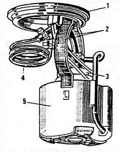
Fig. 2-51. Fuel pump:
1 — pump mounting bracket;
2 — pump mounting clamp;
3 - pump;
4 — damper;
5 - coarse mesh filter.
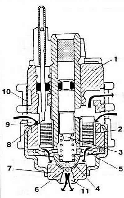
Fig. 2-52. Sectional view of the injector:
1 — body;
2 - winding;
3 - anchor;
4 - shut-off valve;
5 - diaphragm spring;
6 — nozzle hole;
7 — shut-off valve seat;
8 - electrical connector;
9 — annular fuel supply chamber;
10 — filter;
11— nozzle.
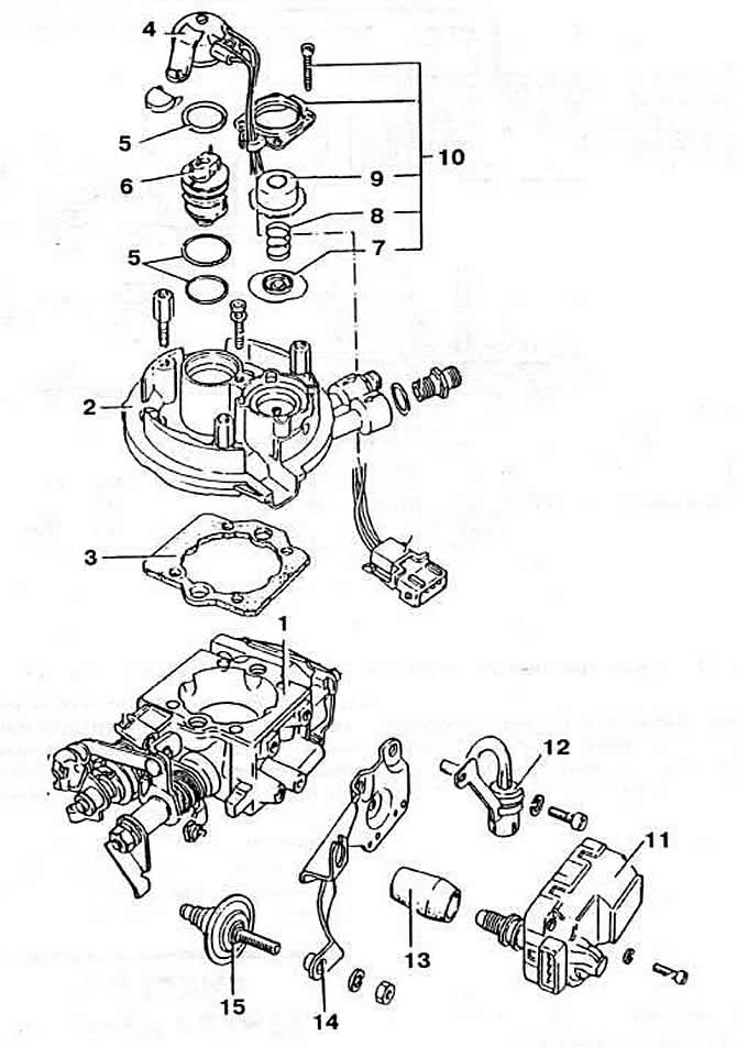
Fig. 2-53. Details of the central injection unit SCV "Mono-Jetronic":
1 — body;
2 - lid;
3 - sealing gasket;
4 - nozzle holder;
5 - sealing ring;
6 — nozzle;
7 - diaphragm;
8 - spring;
9 — lid;
10 - Fuel pressure regulator parts;
11 — idle speed control;
12 — separator;
13 - protective cover;
14 — bracket;
15 — throttle damper.
When each "Ignition Timing" signal is generated, the ECU sends an electrical pulse to the injector winding. Under the action of the magnetic field created, the shut-off valve is attracted to the anchor. Fuel coming through the filter from the annular chamber is sprayed into the intake manifold through six nozzle holes of the injector seat.
(The article is posted on the portal: VWmanual)
When the electrical impulses from the ECU stop, under the influence of the diaphragm spring, the round head of the steam valve sits on the seat, blocking the nozzle openings.
Excess fuel is diverted to the pressure regulator through the top opening of the injector, which ensures the injector is purged, preventing the formation of fuel vapor.
To reduce the voltage at the injector terminals, a ballast resistor is connected in series with it. It is located on the upper support of the right front suspension strut.
The fuel pressure regulator (Fig. 2-54) is mechanical, diaphragm type. It is installed in the central injection unit. The fuel drained from the injector directly affects the regulator diaphragm, which moves, compressing the return spring under a pressure of 1.06±0.06 kgf/cm². As a result, the fuel returns to the tank through the cuff.
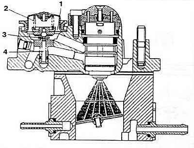
Fig. 2-54. Fuel pressure regulator:
1 - diaphragm;
2 - compression spring;
3 - cuff;
4 — fuel drain channel.
The air intake system includes the air filter, central injection unit, throttle position sensor, intake air temperature sensor, idle speed control valve, and intake manifold.
Air filter by Mann, catalog No.45 152 541 1000 with dry replaceable paper filter element. The filter element is subject to replacement every 30,000 km.
The central injection unit of the Bosch brand, type C 31152, provides fuel injection, fuel pressure regulation, automatic regulation of engine idle speed and determination of the throttle valve position.
The throttle position sensor is a potentiometric type. It is mounted on the throttle shaft. The ECU receives two voltage pulses from the sensor. The value of which is proportional to the throttle opening angle. The signal corresponding to each opening angle is one of the main parameters. Based on which the ECU calculates the main fuel injection time. To prevent the throttle from sticking and errors in measuring the opening angle, its shaft is mounted on two ball bearings.
The sensor potentiometer engine can move along two conductive tracks. At the throttle opening angle from 0 to 24 degrees, the signal to the ECU comes from the first track. These throttle positions correspond to ten reference points entered into the ECU memory. which allows tracking the slightest changes in the angular position of the throttle. As soon as it opens to 18 degrees and up to the full load position, the potentiometer engine simultaneously moves along both tracks. The range of throttle opening angles from 18° to the maximum value corresponds to five reference points in the ECU memory. Thus, at the throttle opening angle from 18 to 24°, two voltage pulses are simultaneously sent to the unit. If the sensor fails, the ECU stops generating fuel injector control pulses.
The position of the sensor on the central injection unit body is set at the factory and should not be changed during operation under any circumstances. In case of sensor failure, both of these units must be replaced as a whole.
The intake air temperature sensor is installed in the intake air duct of the central injection unit. The coolant temperature sensor is screwed into the cylinder head body. Both sensors have a negative temperature coefficient, i.e. their resistance decreases as the temperature increases. The intake air and coolant temperature values are transmitted from the sensor to the ECU in the form of voltage signals.
The idle speed controller (Fig. 2-55) is a DC stepper motor that rotates the throttle shaft.
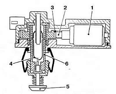
Fig. 2-55. Idle speed control:
1 - DC stepper motor;
2 - worm;
3 - helical gear;
4 - throttle switch;
5 — rod;
6 — lead screw sleeve.
According to the ECU commands, the regulator turns the throttle valve when it goes beyond the angular zone, taking into account the tolerance. corresponding to the idle mode. Due to this, the throttle valve remains practically motionless. thus ensuring a stable idle mode.
The regulator has a built-in microswitch that sends a signal to the ECU about closing the throttle valve, based on which the control unit generates a command to stop fuel supply in the forced idle mode. After the engine crankshaft speed has decreased to a certain value, and also depending on the coolant temperature, fuel injection is resumed by the ECU command and the engine switches to the idle mode. When the throttle valve is in the idle position with a deviation in one direction or another within the tolerance, the control signal is not sent to the regulator. When the throttle valve goes beyond the tolerance, the ECU sends a rectangular voltage signal to the regulator electric motor to restore the required idle speed. If the throttle valve position continues to change, the regulator first receives a continuous signal to quickly return the throttle valve to the position corresponding to the engine idle speed, and then a rectangular signal for the final adjustment of the throttle opening degree. When the control voltage is supplied to the electric motor of the regulator, a gearbox consisting of a worm and a helical gear is activated. Inside the wheel there is a lead screw, onto which the throttle switch housing is screwed or unscrewed depending on the direction of rotation of the wheel. The electrical circuits of the CCS are formed by the ECU with devices connected to it (Fig. 2-72). In the system "Mono-Jetronic" the "RP" engine uses a dual control relay to turn on the fuel pump and supply voltage to the ECU and injector. It is installed in the box on the left under the instrument panel. The protection circuit breaks the fuel pump power supply circuit if the ignition is turned on when the engine is not running (for example, in case of an accident).
The ECU is a digital microcomputer consisting of an analog-to-digital converter, input data calculation and control circuits, a microprocessor, a read-only memory (ROM) and a random-access memory (RAM). Based on information about the throttle valve opening and engine speed, the ECU calculates the basic injector valve opening duration according to its own program, which determines the amount of fuel supplied to the engine. The unit's memory contains 225 values of the basic fuel injection duration, which are determined based on 15 throttle valve positions and 15 engine crankshaft speed steps and which correspond to the excess air coefficient a=1.0 established empirically. Phased with the ignition timing, the basic injection duration can be changed within 1-6 ms in order to lean the working mixture in certain engine operating modes, with the exception of starting, warming up the engine and full load mode, as well as at a coolant temperature below 75°C and a cold exhaust gas oxygen sensor.
When starting a cold engine, if the fuel pump performance decreases due to the battery discharge, the ECU increases the fuel injection duration accordingly for precise dosing of the fuel-air mixture. During engine warm-up, the enrichment degree of the combustible mixture is calculated by the ECU depending on the coolant temperature, and during acceleration - based on information about the engine temperature, the speed of movement and the initial position of the throttle valve, and the number of revolutions. The injection duration also increases as soon as the throttle valve opens at an angle of more than 70°, i.e. in full power mode.
If the engine crankshaft speed exceeds 6200 rpm, the generation of injector control pulses and fuel supply are stopped. When the accelerator pedal is released, provided that the throttle switch rod is pressed, the coolant temperature is above 45°C, and the inlet air temperature is above -15°C, the ECU cuts off the fuel supply. If the inlet air temperature is in the range from -15°C to +10°C, the fuel supply is stopped at 2500 rpm and resumed at 2300 rpm, at an air temperature above 10°C at 1800 and 1300 rpm, respectively.
If one or more system devices fail, such as coolant temperature sensors, intake air temperature, exhaust gas oxygen concentration, throttle position sensor, idle speed controller, the ECU switches to a backup control program, selecting reference values of the required parameters from memory, provided that the ignition system is operating normally. This allows the vehicle to continue moving, excluding engine failure.
The oxygen concentration sensor measures the oxygen content in the exhaust gases. After processing the signals from the oxygen concentration sensor, the ECU adjusts the fuel injection duration.
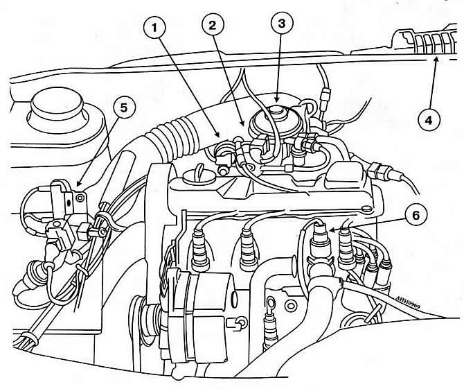
Fig. 2-56. Placement of Mono-Jetronic CVS units in the engine compartment:
1 - idle speed controller
2 — central injection unit
3 — nozzle
4 — ECU
5 - injector ballast resistor
6 - coolant temperature sensor
Visitor comments