
English Русский
Български
Беларускі
Український
Српски
Hrvatski
Română
Polski
Slovenský
Magyar
  |  Articles  |  Sitemap  |  Contacts  |    |
Car maintenance Ford Car maintenance Hyundai Car maintenance Chevrolet Car maintenance BMW Car maintenance Audi Car maintenance Opel Car maintenance AvtoVAZ
VWmanual.ru


Main   Passat   Golf   Polo   Touareg   Tiguan   Sharan   Transporter   Others  
Passat B2 (1981-1988) Passat B3 (1988-1993) Passat B4 (1988-1996) Passat B5 (1996-2005) Passat B6 (2005-2010)

System self-diagnosis (VW Passat B4)

  • Main
  • Passat
  • Passat B4
  • 8-valve engine
  • Fuel injection «Mono-Jetronic»
  • System self-diagnosis
            0


Electronic SCV "Mono-Jetronic" has a self-diagnostic system. The injection system ECU includes a read-only memory (ROM) that detects, stores and indicates some system faults that occur during operation. Of all possible faults in the injection system, only one is stored. Only after polling the ROM, eliminating the detected fault and erasing its code, can other possible faults be successively detected by polling the contents of the ROM again.

A request for a specific fault related to the operation of the oxygen sensor in the exhaust gases can only be made after a test drive lasting at least 10 minutes, if no other fault occurs.

The ROM also remembers faults caused by temporary damage to the wiring or contacts. If such faults do not recur within approximately eight engine starts, their codes are automatically erased from the memory.

Request for fault codes entered in the ROM. The fault codes entered in the ROM of the electronic control unit are displayed using a control lamp located in the instrument cluster (Fig. 2-68). When the ignition is turned on, the lamp lights up. After the engine is started, if no serious faults in the engine operation are detected, the lamp goes out.
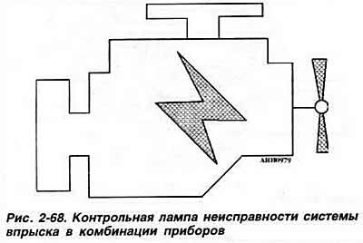
Request for fault codes entered in the ROM. The fault codes entered in the ROM of the electronic…


When polling the contents of the self-diagnostic system ROM, the malfunction indicator lamp should flash.


Display of fault codes. When interrogating the self-diagnostic ROM, four-digit fault codes are displayed as a sequence of groups of flashes of the fault indicator lamp with intervals between the groups of flashes lasting 2.5 seconds, during which the indicator lamp does not light. Each character of the four-digit code corresponds to a number or group of flashes from 1 to 4. If no faults are detected in the system, the code 4-4-4-4 is displayed. At the end of the display of the code sequence, the code 0-0-0-0 is displayed. In this case, the indicator lamp flashes at constant intervals of 2.5 seconds.

Entering fault codes into the control unit ROM occurs only when the ignition is on.

The four groups of flashes of the requested fault code appear after the output of a start signal, during which the indicator lamp lights up, and a pause of 2.5 seconds, during which the indicator lamp does not light up. After the output of the fourth group of flashes, another pause of 2.5 seconds follows. The corresponding flash code is then marked by means of a start signal until the ignition is switched off or the engine speed exceeds 2500 rpm.

Example:
  • the control lamp lights for 2.5 sec;
  • the control lamp goes out for 2.5 s.

The starting signal is given:
  • the lamp flashes twice;
  • the lamp goes out for 2.5 sec;
  • the lamp flashes three times;
  • the lamp goes out for 2.5 sec;
  • the lamp flashes four times;
  • the lamp goes out for 2.5 sec;
  • the lamp flashes twice;
  • the lamp goes out for 2.5 sec.

Thus, the code 2-3-4-2 is issued. After this, the cause of the malfunction is determined according to the table of malfunction codes. After eliminating the malfunction, the code of which was entered into the ROM, its code should be erased from the contents of the ROM.
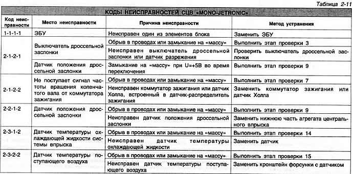
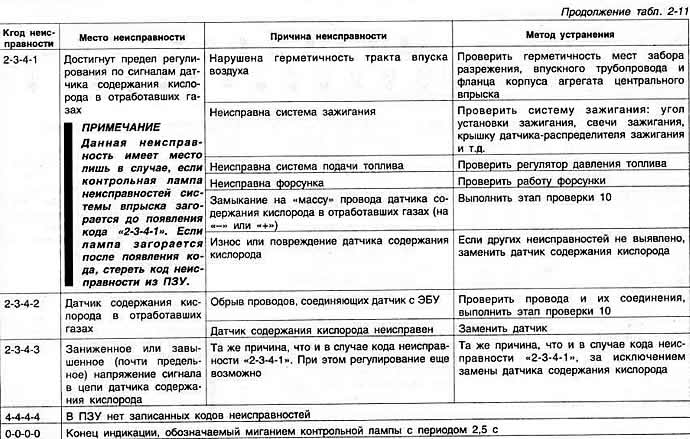
Thus, the code 2-3-4-2 is issued. After this, the cause of the malfunction is determined according…

Thus, the code 2-3-4-2 is issued. After this, the cause of the malfunction is determined according…

After this, the ROM is again polled for the presence of the next fault.

Interrogation of the fault ROM. When interrogating the fault ROM, the following sequence of operations must be strictly observed:
  • demand ROM faults:
  • troubleshooting the detected fault;
  • erasing the code of the corrected error from the contents of the ROM;
  • new poll of the fault ROM.

Thus, a request to detect the next malfunction is possible only after the previous one has been eliminated and its code has been erased.

If no other fault is detected, perform a new interrogation of the fault memory after a test drive of at least 10 minutes.

In this case, the fault ROM interrogation is performed as follows: Check the reliability of all wiring connections, the serviceability of the fault indicator lamp and fuse N918. Start and warm up the engine to normal operating temperature and leave it to idle. Do not increase the crankshaft speed during the checks.

The original information is posted on the website (vwmanual.ru)

Note: If the engine does not start, before starting the test, turn on the starter for 6 seconds and leave the ignition on.


Move the gearshift lever protective cover up and connect the red terminal "1" of the connector located next to the gearshift lever with a 5-wire ground connection (Fig. 2-69). On vehicles that do not have such a connector, connect the yellow-black wire of the ignition coil connector with a wire to the ground for at least 5 s (Fig. 2-70). The system malfunction indicator lamp in the instrument cluster should start flashing.
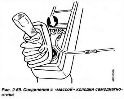
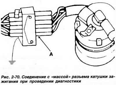
Move the gearshift lever protective cover up and connect the red terminal «1» of the connector…


Move the gearshift lever protective cover up and connect the red terminal «1» of the connector…


Count and record the number of blinks in each group. Eliminate the detected malfunction.

Erase the code of the eliminated fault. Continue checking until the code 0-0-0-0 appears, indicating the end of the fault code display. The output of the code 4-4-4-4 means there are no faults in the injection system.

Erase contents of fault memory. Switch off ignition. Connect red terminal of connector or yellow-black wire of ignition coil connector to ground with wire. Switch on ignition. After 5 s disconnect ground wire. Code of previous fault is deleted from fault memory.

Note. The table of fault codes also contains instructions on how to eliminate them. The last column of the table indicates the stages of checking the electrical circuits of the system through the terminals of the ECU connector according to the table below "Checking the electrical parameters of the SCV "Mono-Jetronic" through the ECU connector terminals".

Codes 2-3-4-1 and 2-3-4-3 can only be erased by disconnecting the electronic control unit connector for at least 30 s.
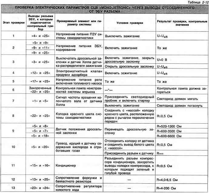
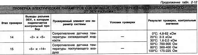
Codes 2-3-4-1 and 2-3-4-3 can only be erased by disconnecting the electronic control unit connector…

Codes 2-3-4-1 and 2-3-4-3 can only be erased by disconnecting the electronic control unit connector…

This article is available at russian, bulgarian, belarusian, ukrainian, serbian, croatian, romanian, polish, slovak, hungarian
The text has been checked: Kolesnikov Artem

Share information:

Previous articles
Fuel pump
Checking and adjusting the fuel injection system «MONO-JETRONIC»
Central fuel injection system «MONO-JETRONIC»
Next articles
Checking the electrical circuits of the system
Checking the engine idle speed
Checking and adjusting the throttle valve opening
Checking the idle speed control valve
Checking the ignition retard control valve
Checking the fuel pressure regulator


Similar articles from other manuals for VW cars:
Cooling system data Golf 1 (1974-1984, petrol)
Self-diagnosis of the injection system Polo 3 (1995-2003)
Emergency alarm system Touareg 1 (2002-2006)
Removal and installation of lubrication system elements Tiguan 1 (2007-2015)
Checking the operation of the lighting system Sharan 1 (1995-2000)
Headlight Wash System Transporter T4 (1990-2003)
ESP stabilization system and ASR traction control system Caddy 3 (2003-2010)
Link to this page in different formats


Visitor comments


No comments yet


How much will 41 + 33 =


Passat B6 
  • General information
  • User manual
  • Maintenance
  • Petrol engine 1.6L
  • Engine repair
  • Cooling and lubrication system
  • Fuel injection system
  • Petrol engine 2.0L
  • Engine repair
  • Lubrication system
  • Cooling system
  • Fuel and exhaust systems
  • Diesel engine 2.0L
  • Engine repair
  • Cooling and lubrication system
  • Fuel and exhaust systems
  • Transmission
  • Clutch
  • Mechanical gearbox
  • Automatic gearbox
  • Drive shafts
  • Chassis
  • Wheels and tires
  • Car suspension
  • Steering
  • Brake system
  • Body
  • Exterior (external elements)
  • Electrical equipment
  • Power devices
  • Lighting and appliances
  • Electrical circuits
Passat B5 
  • General information
  • User manual
  • Weekly checks
  • Maintenance
  • Power unit
  • Engine repair
  • Cooling system
  • Fuel system (petrol)
  • Fuel system (diesel)
  • Engine management
  • Exhaust system
  • Transmission
  • Clutch
  • Car gearbox
  • Drive shafts
  • Chassis
  • Car suspension
  • Wheels and tires
  • Steering
  • Brake system
  • Body
  • Exterior (external elements)
  • Interior (internal elements)
  • Doors and covers
  • Ventilation and heating
  • Electrical equipment
  • Power devices
  • Lighting and appliances
  • Electrical circuits
Passat B4 
  • General information
  • User manual
  • Maintenance
  • Technical data
  • 8-valve engine
  • Engine repair
  • Cooling and lubrication system
  • Supply system
  • Ignition system
  • Fuel injection «Mono-Jetronic»
  • Control system «Mono-Motronic»
  • Control system «Digifant»
  • Control system «Simos»
  • 16-valve engine
  • Engine repair
  • Cooling and lubrication system
  • Fuel injection «K-Jetronic»
  • Control system «KE-Motronic»
  • Control system «Digifant»
  • Diesel engine
  • Engine repair
  • Cooling and lubrication system
  • Power and control system
  • Turbocharging system
  • Digital control system
  • Transmission
  • Clutch
  • Manual gearbox
  • Hydromechanical gearbox
  • Front wheel drive
  • Chassis
  • Car suspension
  • Steering
  • Brake system
  • Body
  • Body elements
  • Electrical equipment
  • Power devices
  • Lighting and appliances
  • Electrical circuits
Passat B3 
  • General information
  • User manual
  • Driving Tips
  • Maintenance instructions
  • Technical data
  • Power unit
  • Engine repair
  • Ignition system
  • Lubrication system
  • Cooling system
  • Supply system
  • Petrol injection system
  • Diesel engine
  • Exhaust system
  • Transmission
  • Clutch
  • Car gearbox
  • Chassis
  • Suspension
  • Steering
  • Brake system
  • Wheels and tires
  • Body
  • Exterior
  • Interior
  • Heating system
  • Electrical equipment
  • Power devices
  • Lighting system
  • Equipment and devices
  • Wiper system
  • Electrical circuits
Passat B2 
  • General information
  • Introduction to instructions
  • User manual
  • Power unit
  • Engines 4-cylinder FZ
  • Engines 4-cylinder
  • Engines 5-cylinder
  • Transmission
  • Clutch
  • Four-speed gearbox
  • Five-speed gearbox
  • Hydromechanical gearbox
  • Front wheel drive
  • Chassis
  • Front suspension
  • Rear suspension
  • Steering
  • Brake system
  • Body
  • Body elements
  • Electrical equipment
  • Equipment and devices
  • Electrical circuits
VWmanual.ru © 2016-2026 | Mobile version | News and articles | Sitemap: EN BG BY UA RS HR RO PL SK HU | Write message | Site search
Passat B2 • Passat B3 • Passat B4 • Passat B5 • Passat B6 • Golf 1, diesel • Golf 1, petrol • Golf 2, petrol • Golf 2 • Golf 3 • Golf 4 • Golf 5 • Polo 3 • Polo 4 • Touareg 1 • Tiguan 1 • Sharan 1 • Transporter T3 • Transporter T4 • LT 28 • LT 2D • Beetle • Caddy 3 •
Our website uses cookies to ensure functionality and convenience.