



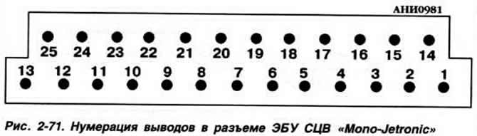
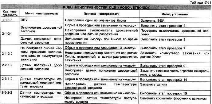
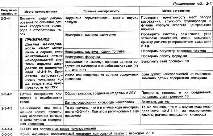
The check is performed with a working and well-charged storage battery, with an undamaged and securely connected "ground" wire of the engine, with a working fuel pump and its switch, with whole fuses.
Disconnect the ECU connector of the injection system and perform checks according to the table "Checking the electrical parameters of the SCV "Mono-Jetronic" through the ECU connector terminals".
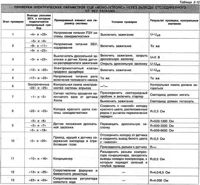
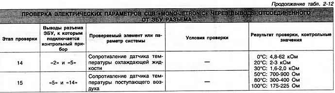
Warning: Do not connect the measuring instrument probes (ohmmeter or voltmeter) to the connector terminals. It is recommended to connect the device to the supply wires from the back of the connector, to access which it is necessary to move the protective plastic cover of the connector. The most acceptable way to carry out measurements is to use a special adapter that is connected to the connector and has the same terminal numbering.
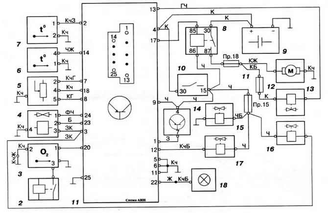
Fig. 2-72. Connection diagram of the SCV "Mono-Jetronic" "RP" engines manufactured before 1993:
1 — ECU;
2 — relay for switching on the heating of the oxygen content sensor in the exhaust gases;
3 - exhaust gas oxygen sensor;
4 - idle speed controller;
5 - throttle position sensor;
6 — intake air temperature sensor;
7 - coolant temperature sensor;
8 — fuel pump relay;
9 — battery;
10 - ignition switch;
11 — injector ballast resistor;
12 — fuel pump;
13 — nozzle;
14 — switch;
15 — electromagnetic shut-off valve of the adsorber;
16 — ignition delay control valve;
17 — electromagnetic valve for purging the adsorber;
18 — fuel injection system malfunction indicator lamp.
Visitor comments