



Contents: AGX engine up to 01.99: ↓ AGX engine since 02.99: ↓ AHD engine up to 04.98: ↓ AHD engine since 05.98: ↓ ANJ Engine: ↓ Engines ARA, VVE, VVE: ↓ Checking the operation of the EGR…↓ Checking the EGR solenoid valve ↓
The EGR system's performance is checked using "Function 04" (basic installations). With this procedure, the EGR valve operates in a cycle every 10 seconds so that in the measured value block 003 the extreme value for the EGR valve is (air flow meter) could be read in field 3 of the display.
1. Connect the VAG 1551 (VAG 1552) fault code reader and select the engine control unit with "Address TIN" 01. The engine should be idling. The display should show the following information:
- Quick data search HELP
- Select function XX
2. Press "04" to select the "Start Basic Settings" function and press "Q". The display should show the following information:
- Basic HELP settings
- Enter group number XXX
3. Press "0", "03" to select the "Display Group 3" function and press "Q".
Caution! If the display shows "Function not detected or cannot be performed at this time," check the EGR valve operation using the final diagnostics.
The display should show the following information:
- Basic settings 3
- 900 rpm EGR inactive 500 mg/stroke 0%
Display field 2 should alternate every 10 seconds between EGR active and EGR inactive. The values of fields 3 and 4 of the display should change within the following ranges:
AGX engine up to 01.99:
EGR is inactive
Specified value
- Field 3: 480-520 mg/stroke
- Field 4: 0-5%
EGR is active
Specified value
- Field 3: 270-400 mg/stroke
- Field 4: 95-100%
AGX engine since 02.99:
EGR is inactive
Specified value
- Field 3: 290-450 mg/stroke
- Field 4: 0%
EGR is active
Specified value
- Field 3: 280-350 mg/stroke
- Field 4: 99%
AHD engine up to 04.98:
EGR is inactive
Specified value
- Field 3: 450-470 mg/stroke
- Field 4: 0-5%
EGR is active
Specified value
- Field 3: 240-280 mg/stroke
- Field 4: 95-100%
AHD engine since 05.98:
EGR is inactive
Specified value
- Field 3: 430-480 mg/stroke
- Field 4: 0-5%
EGR is active
Specified value
- Field 3: 190-240 mg/stroke
- Field 4: 95-100%
ANJ Engine:
EGR is inactive
Specified value
- Field 3: 400-500 mg/stroke
- Field 4: 0%
EGR is active
Specified value
- Field 3: 100-250 mg/stroke
- Field 4: 99%
Engines ARA, VVE, VVE:
EGR is inactive
Specified value
- Field 3: 420-500 mg/stroke
- Field 4: 0%
EGR is active
Specified value
- Field 3: 190-260 mg/stroke
- Field 4: 99%
Caution! If field 3 of the display shows 550 mg/stroke, check the air flow meter. Field 3 of the display shows the pressure, which depends accordingly on the altitude above sea level. Specification values are calculated at 0 m above sea level. If the obtained values differ significantly, check in field 3 the difference between the readings with active and inactive EGR, which should be at least 100 mg/stroke.
4. If the specified value is not reached: check the mechanical EGR valve, vacuum lines, and the electromagnetic EGR valve. Press "→" and "06" for the "Data Transfer Completion" function and press "Q".
Checking the operation of the EGR system through final diagnostics of the control elements
The functionality of the EGR system and air flow meter can be checked using a final control element diagnostic and the simultaneous display of measured value block "03." To do this, the final control element "EGR Valve" must be activated and the test must be terminated by pressing "C." After this procedure, the EGR valve continues to cycle so that the extreme values for the EGR system (air flow meter) could be read in the measured value block "003" (display field 3).
5. Connect the VAG 1551 (VAG 1552) fault code reader and select the engine control unit with "Address word" 01. The engine should be idling. The display should show the following information:
- Quick data search HELP
- Select function XX
6. Press "03" to select the "Final Controls Diagnostics" function. The display should show the following information:
- Quick data search Q
- 03 - Final diagnostics of controls
Important! Individual control checks only last 30 seconds. During this time, you must make several entries and read the measured values during the following procedures. So please read the following work steps first and familiarize yourself with the procedure.
7. Confirm your entry by pressing the "Q" button. The display should show the following information:
- Final diagnostics of controls →
- Starting the injector operation
8. Press the "→" button. The display should show the following information:
- Final diagnostics of controls →
- EGR valve
9. Press the "C" button. Press "08" to select the "Read Block of Measured Values" function and confirm with the "Q" button. The display should show the following information:
- Reading the measured value block HELP
- Enter group number XX
10. Press "08" to select the "Display Group 03" function and confirm with the "Q" button. The display should show the following information:
Reading the measured value block 3,840 rpm 272 mg/stroke 268 mg/stroke 94%
11. The values in fields 3 and 4 must vary within the following range:
AGX engine
The specified value in field 3
- Lower level: 230-420 mg/stroke.
- Upper range: 420-500 mg/stroke.
The specified value in field 4
- Lower level: 2-5%.
- Upper range: 90-95%
AHD engine
The specified value in field 3
- Lower level: 230-320 mg/stroke.
- Upper range: 400-500 mg/stroke.
The specified value in field 4
- Lower level: 2-5%.
- Upper range: 90-95%
12. If the specified values are not achieved: check the mechanical EGR valve, vacuum lines, and the electromagnetic EGR valve. Press "→" and "06" to select the "Data Transfer Completion" function, and then press "Q.".
Checking the EGR solenoid valve
13. Disconnect connector 2 from EGR valve 1 (figure 3.50). Measure the valve resistance. Set value: 14-18 Ohm.
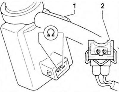
Figure 3.50. Checking the resistance of the EGR solenoid valve.
14. If the specified value is not achieved: replace the EGR solenoid valve.
15. If the set value is reached: turn on the ignition. Measure the voltage between valve terminal 1 and engine ground (figure 3.46). Set value: battery voltage.
If the set value is not reached: turn off the ignition.
Vehicles with a 68-pin control unit connector
16. Connect the VAG 1598/18 tester to the control unit wiring. The engine control unit is not involved in the process.
17. Check the resistance of the wires between the tester and the connector: contact 1 + socket 68, contact 2 + socket 25. Wire resistance: max. 1.5 ohms. Also check the wires for short circuits to each other, to ground, and to the positive terminal. Set value: ∞ Ohm.
Vehicles with 121-pin control unit connector
18. Connect the VAG 1598/31 tester to the control unit wiring. The engine control unit is not involved in the process.
19. Check the resistance of the wires between the tester and the connector: contact 1 + socket 1 + 2, contact 2 + socket 61. Wire resistance: max. 1.5 ohms. Also check the wires for short circuits to each other, to ground and to the positive terminal. Set value: ∞ Ohm
On all cars
20. If no faults are found: disconnect the tester.
21. Replace the fuel injection control unit if necessary.
Visitor comments