



2. Disconnect the wiring connector 1 from the crankshaft speed sensor (figure 3.52).
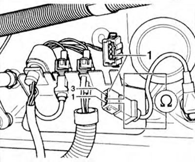
Figure 3.52. Checking the resistance of the crankshaft speed sensor.
3. Measure the resistance between pins 1 and 2 of the connector. The specified value is 1.1-1.6 Ohms.
4. If the specified value is not achieved, replace the engine speed sensor.
On vehicles with a 68-pin control unit connector
5. If the specified value is reached, connect the VAG 1598/18 tester to the engine control unit wiring harness. Check the wires between the tester and the 3-pin connector for continuity: pin 1 + socket 33, pin 2 + socket 8, pin 3 + socket 1 (figure 3.53). Specified value: max 1.5 ohm.
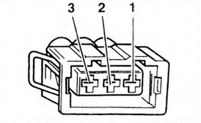
Figure 3.53. Checking the resistance between the tester and the 3-pin connector for interruption of the circuit.
6. Check the wires of the 3-pin connector for short circuit. Specified value: ∞ Ohm.
7. If no fault is found in the wires, then replace the engine control unit.
On vehicles with a 121-pin control unit connector
8. If the specified value is reached, connect the VAG 1598/31 tester to the engine control unit wiring harness. Check the wires between the tester and the 3-pin connector for continuity: pin 1 + socket 102, pin 2 + socket 110, pin 3 + socket 86 (figure 3.53). Specified value: max 1.5 ohm.
9. Check the wires of the 3-pin connector for short circuit. Set value: ∞ Ohm.
10. If no fault is found in the wires, then replace the engine control unit.
Visitor comments