



Contents: On AGX engines from 02.99, AHD from…↓ On vehicles with a 68-pin control…↓ On vehicles with a 121-pin control…↓
1. Connect the VAG 1551 tester and, by entering "01" "Engine electronics", select the engine control unit. The engine should be idling. The display should show the following information:
- Fast data exchange HELP
- Dial function XX
2. Press "08" to select the "Read Block of Measured Values" function and confirm with the "Q" button. The display should show the following information:
- Reading the measured value block HELP
- Enter group number XX
3. Press "0" and "10" to select the "Display Group 10" function and press "Q". Accelerate the vehicle in 2nd gear, starting at 1500 rpm, with the accelerator pedal fully depressed. Press PRINT on the VAG 1551 tester at 3000 rpm. The accelerator pedal should be fully depressed at this time. The display should show the following information:
- Reading block of measured values 10 →
- 830 mg/stroke 1027 bar 1850 bar 100%
The set value is displayed in field 4 of the display (accelerator pedal position).
4. If the specified value is not achieved, repeat the test and accelerate the vehicle with the accelerator pedal fully depressed. The display should show the following information:
- Reading block of measured values 10 →
- 830 mg/stroke 1027 bar 1850 bar 100%
The set value is displayed in field 1 of the display. AGX engines: over 400 mg/stroke (intake air). AHD, ANJ, ARA, VBE, BBF engines: over 700 mg/stroke (intake air).
5. If the specified value is not achieved, replace the flow meter.
6. If the display constantly shows a value of approximately 500 mg/stroke, press "→".
7. Press "06" to select the "Quick Data Exchange" function and confirm by pressing the "Q" button.
8. Turn off the ignition.
On AGX engines up to 01.99, AHD up to 04.98
9. Disconnect connector 1 from flow meter 2 (figure 3.66). Turn on the ignition.
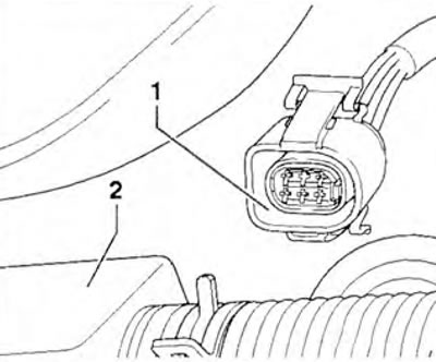
Figure 3.66. On AGX engines up to 01.99, AHD up to 04.98: disconnect connector 1 from flow meter 2.
10. Measure the voltage between the terminals of the air flow meter connector (figure 3.67).
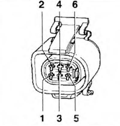
Figure 3.67. Measure the voltage between the air flow meter connector contacts.
| Connector contacts | Specified value |
| 3 + "mass" | ≈ battery voltage |
| 3 + 5 | |
| 1 + "mass" | About 5 V |
| 1 + 5 |
11. If the specified value is not reached, turn off the ignition and connect the VAG 1598/18 tester to the engine control unit wiring harness.
12. Check the wires between the tester and the socket for continuity: pin 1 + socket 19, pin 2 + socket 33, pin 3 + socket 23, pin 5 + socket 1, pin 6 + socket 13 (figure 3.67). Specified value: max 1.5 ohm.
13. Check the ground wire connection between the needle position sensor and the fuel injection system wiring. Specified value: max 1.5 ohm.
14. Check the wires for short circuits, short circuits to positive or negative poles.
15. If there are no faults in the wires, replace the fuel injection system control unit.
On AGX engines from 02.99, AHD from 05.98, ANJ, ARA, VBE, BBF
16. Disconnect the connector from the flow meter and turn on the ignition.
17. Measure the voltage between the terminals of the air flow meter connector (figure 3.68).
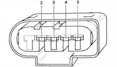
Figure 3.68. Measure the voltage between the air flow meter connector contacts.
| Connector contacts | Specified value |
| 2 + "mass" | ≈battery voltage |
| 2 + 3 | |
| 4 + "mass" | About 5 V |
| 4 + 3 |
18. If the set value is not reached, turn off the ignition.
On vehicles with a 68-pin control unit connector
19. Connect the VAG 1598/18 tester to the engine control unit wiring harness. Check the wires between the tester and the connector for continuity: pin 2 + sockets 23, 45, 68, pin 3 + socket 21, pin 4 + socket 19, pin 5 + socket 13 (figure 3.68). Specified value: max 1.5 ohm.
20. Check the connector wires for short circuit.
Set value: ∞ Ohm.
21. If there are no faults in the wires, replace the fuel injection system control unit.
On vehicles with a 121-pin control unit connector
22. Connect the VAG 1598/31 tester to the engine control unit wiring harness. Check the wires between the tester and the connector for continuity: pin 2 + sockets 1 and 2, pin 3 + socket 49, pin 4 + socket 30, pin 5 + socket 68 (figure 3.68). Specified value: max 1.5 ohm.
23. Check the connector wires for short circuit.
Set value: ∞ Ohm.
24. If there are no faults in the wires, replace the fuel injection system control unit.
Visitor comments