



1. Connect the VAG 1551 tester and, by entering "01" "Engine Electronics", select the engine control unit. The engine should be idling. The display should show the following information:

2. Press "08" to select the "Read measured value block" function and confirm by pressing the "Q" button. The display should show the following information:

3. Press "010" to select the "Display Group 10" function and press "Q". The display should show the following information:

4. Check the amount of air passed in field 1 of the display.
Specification value:
- AGR engine: 230-420 mg/h.
- ALH Engine: 200-390 mg/h.
- ASV engine: 210-420 mg/h.
5. If the specified value is not achieved, check the exhaust gas recirculation.
6. If the set value is reached, accelerate the vehicle in second gear with the accelerator pedal fully depressed (revolutions approximately 1500 rpm).
7. Press PRINT on the VAG 1551 at approximately 3000 rpm. The accelerator pedal should be fully depressed at this point. The display should show the following information:

The specification value in field 4 of the display should be 100%.
8. If the specified value is not reached, repeat the test with the accelerator pedal fully depressed. The display should show the following information:

The specification value in field 1 of the display must be greater than 730 mg/h.
9. Click "→".
10. Press "06" to select the "Complete Output" function and confirm by pressing the "Q" button.
11. Turn off the ignition.
12. If the specified value is not achieved, replace the air flow meter.
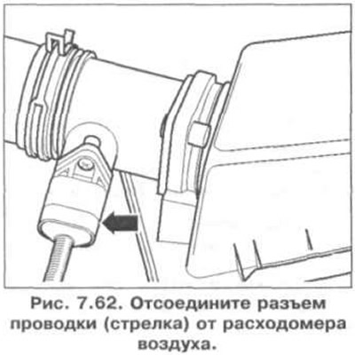
13. If field 1 displays a constant value of 550 mg/h, disconnect the wiring connector (arrow) from the air flow meter (Fig. 7.62).
14. Turn off the ignition.
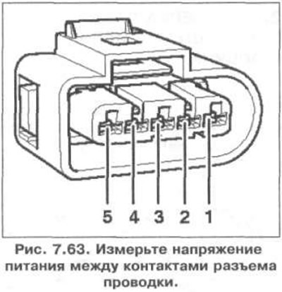
15. Measure the supply voltage between the contacts of the wiring connector (Fig. 7.63).
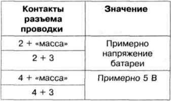
16. If the set value is not reached, turn off the ignition.
17. Connect the VAG 1598/22 tester to the engine control unit wiring harness (fig. 7.38).
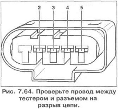
18. Check the wire between the tester and the connector for open circuit: contact 1 and socket 2, contact 2 and socket 28, contact 3 and socket 4, contact 4 and socket 50, contact 5 and socket 52 (Fig. 7.64). Specified value: 1.5 Ohm.
19. Additionally check the wires for short circuits to each other, to the vehicle ground and to the positive battery terminal. Specification resistance: ∞ Ohm.
20. If no fault is found in the wires, replace the engine control unit.
Visitor comments