
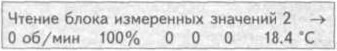
2. Click «08» to select a function «Reading a block of measured values» and confirm by pressing the button «Q». The display should show the following information:
3. Select the desired group. Click «002» for selection «Group 2 display» and confirm by pressing the button «Q». The display should show the following information:
Check the position of the accelerator pedal in field 2. The pedal should not be depressed and the display should show 0.0%. Check in addition readings in zone 3 at idle speed. The display should show 010.
4. Press the pedal all the way down and observe fields 2 and 3 of the display. The display should show the following information:
The percentage of pressing the accelerator pedal should increase gradually. The display should show 100%. Check the reading in zone 3 at idle speed. The display should show 000.
5. If the set value is not reached:
- click «→»;
- click «06» to select a function «Output Completion» and confirm by pressing the button «Q»;
- turn off the ignition;
- adjust the accelerator pedal position sensor.
6. If the display does not change or is unstable, check in the following order:
- click «→»;
- click «06» to select a function «Output Completion» and confirm by pressing the button «Q»;
- turn off the ignition;
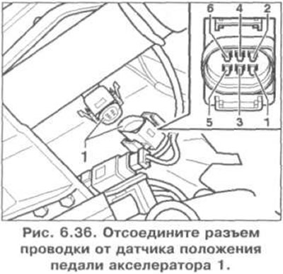
- Disconnect the wiring connector 1 from the accelerator pedal position sensor (pic. 7.36);
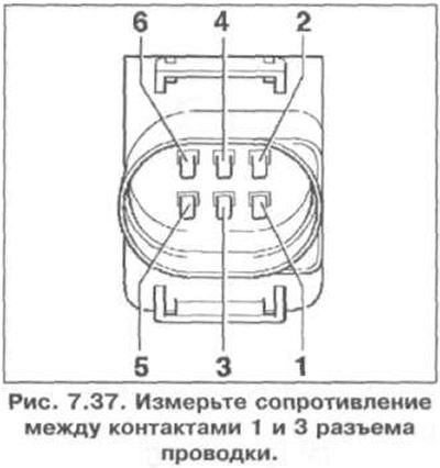
- measure the resistance between pins 1 and 3 of the harness connector (pic. 7.37). Set value: accelerator pedal in the idle position - 1.0-1.5 kOhm, accelerator pedal in the fully depressed position - 1.5-2.5 kOhm;
- measure the resistance between pins 2 and 6 of the harness connector. Set value: accelerator pedal in the idle position - 0.8-1.5 kOhm;
- check the idle switch on the accelerator pedal position sensor. To do this, measure the resistance between pins 4 and 6 of the harness connector. Reference value: accelerator pedal in idle position - max. 1.5 kOhm, accelerator pedal fully depressed - ∞ Ohm.
7. If the specified value is not reached, replace the accelerator pedal position sensor.
8. If the set value is reached:
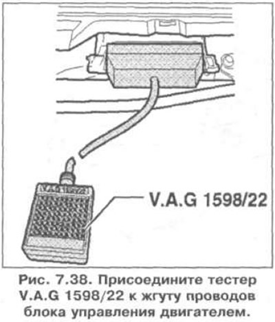
- connect the VAG 1598/22 tester to the wiring harness of the engine control unit (pic. 7.38);
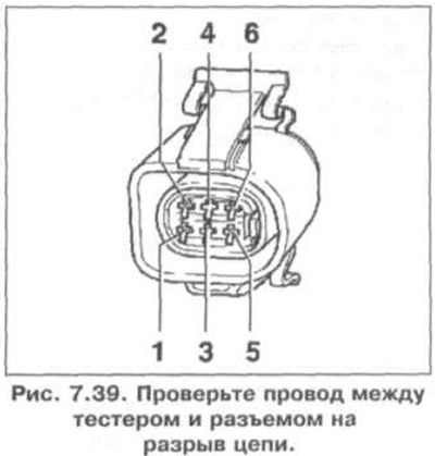
- check the wire between the tester and the connector for an open circuit: pin 1 and slot 24, pin 2 and slot 11, pin 3 and slot 23, pin 4 and slot 12, pin 5 and slot 8, pin 6 and slot 25 (pic. 7.39) Set value: 1.5 ohm;
- additionally check the wires for shorting one to the other, to «mass» vehicle and to the positive pole of the battery. Specification resistance: ∞ Ohm.
9. If no fault is found in the wires, replace the engine control unit.
Visitor comments