
2. Click «08» to select a function «Reading a block of measured values» and confirm by pressing the button «Q». The display should show the following information:
3. Click «007» to select a function «Group 7 display» and press «Q». The display should show the following information:
Check the coolant temperature value in field 4. It should increase smoothly without delay. In a fault condition, the fuel temperature is displayed.
4 Press «→».
5. Click «06» to select a function «Output Completion» and confirm by pressing the button «Q».
6. Turn off the ignition.
7. If there is no real display in field 4 or fuel temperature is displayed, check the coolant temperature sensor and wires:
- click «→»;
- click «06» to select a function «Output Completion» and confirm by pressing the button «Q»;
- turn off the ignition;
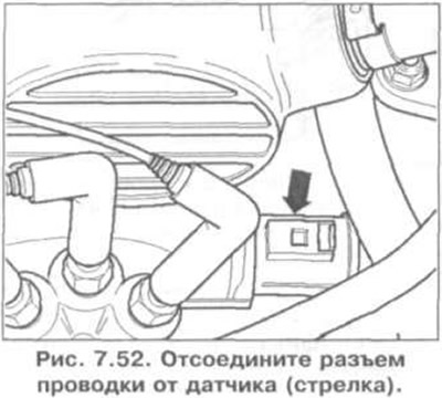
- disconnect the wiring connector from the sensor (arrow) (pic. 7.52).
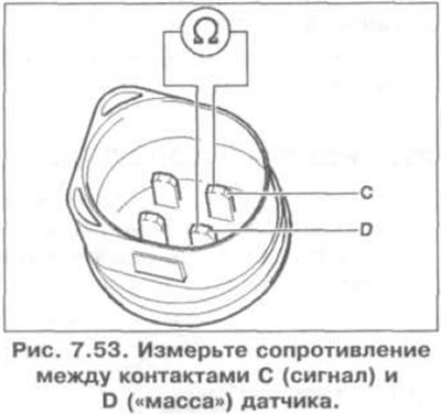
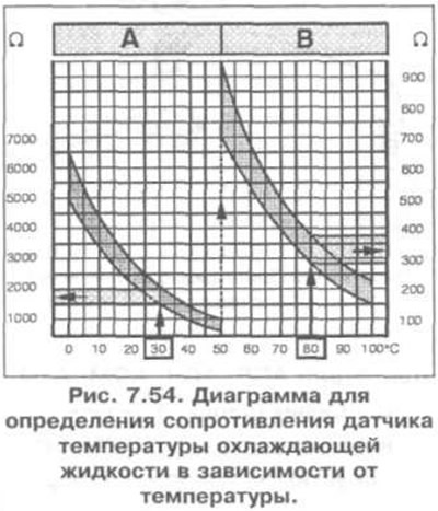
- measure the resistance between pins C (signal) and D («weight») sensor (pic. 7.53). The set value is shown in fig. 7.54. Area A shows resistance in the temperature range 0-50°C, area B shows resistance in the temperature range 50-100°C. For example, a temperature of 30°C corresponds to a resistance of 1500-2000 ohms; a temperature of 80°C corresponds to a resistance of 275-375 ohms.
8. If the specified value is not reached, replace the sensor.
9. If the set value is reached:
- connect the VAG 1598/22 tester to the wiring harness of the engine control unit (rice. 7.38);
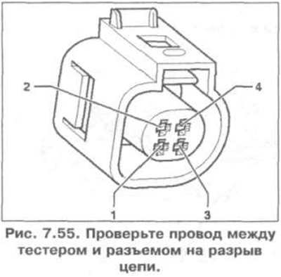
- check the wire between the tester and the connector for an open circuit: pin 1 and slot 70, pin 3 and slot 54 (pic. 7.55). Set value: 1.5 ohm;
- additionally check the wires for an open circuit. Specification resistance: ∞ Ohm.
10. If no fault is found in the wires, replace the engine control unit.
Visitor comments