



- Fast data exchange HELP
- Dial function XX
2. Press "08" to select the "Read Block of Measured Values" function and confirm with the "Q" button. The display should show the following information:
- Reading the measured value block HELP
- Enter group number XX
3. Press "007" to select the "Display Group 007" function and press "Q". The display should show the following information:
- Reading measured value block 7 →
- 15.4°C 15.9°C 16.7°C
4. Check the coolant temperature value in field 4. It should rise smoothly, without delay. In fault condition, fuel temperature is displayed.
5. If field 4 does not display actual temperature or displays fuel temperature, check the coolant temperature sensor and wires.
6. Click "→".
7. Press "06" to select the "Quick Data Exchange" function and confirm by pressing the "Q" button.
8. Turn off the ignition.
9. Disconnect the wiring connector from the sensor (figure 3.54). Measure the resistance between pins 1 and 3 of the sensor. The specified value is shown in the figure 3.55. Area A shows the resistance in the temperature range of 0-50°C, area B shows the resistance in the temperature range of 50-100°C. For example, a temperature of 30°C corresponds to a resistance of 1500-2000 ohms; a temperature of 80°C corresponds to a resistance of 275-375 Ohms.
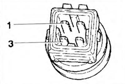
Figure 3.54. Checking the resistance of the coolant temperature sensor.
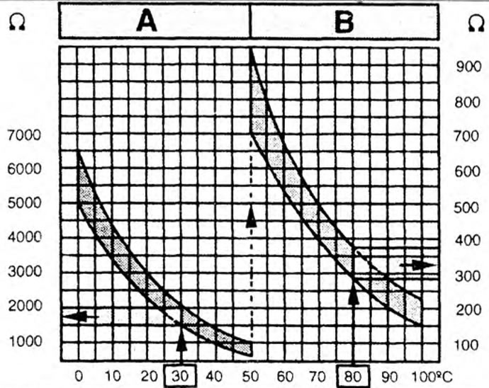
Figure 3.55. Diagram for determining the resistance of the coolant temperature sensor depending on the temperature.
10. If the specified value is not achieved, replace the sensor.
On vehicles with a 68-pin control unit connector
[View the original on this portal: VWmanual.ru]
11. If the specified value is reached, connect the VAG 1598/18 tester to the engine control unit wiring harness. Check the wires between the tester and the 4-pin connector for continuity: pin 3 + socket 33, pin 1 + socket 14 (figure 3.56). Specified value: max 1.5 ohm.
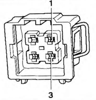
Figure 3.56. 4-pin coolant temperature sensor connector.
12. Check the wires of the 4-pin connector for short circuit. Set value: ∞ Ohm.
13. If no fault is found in the wires, then replace the engine control unit.
On vehicles with a 121-pin control unit connector
14. If the specified value is reached, connect the VAG 1598/31 tester to the engine control unit wiring harness. Check the wires between the tester and the 4-pin connector for continuity: pin 3 + socket 104, pin 1 + socket 112 (figure 3.56). Set value: max 1.50 m.
15. Check the wires of the 4-pin connector for short circuit. Set value: ∞ Ohm.
16. If no fault is found in the wires, then replace the engine control unit.
Visitor comments