



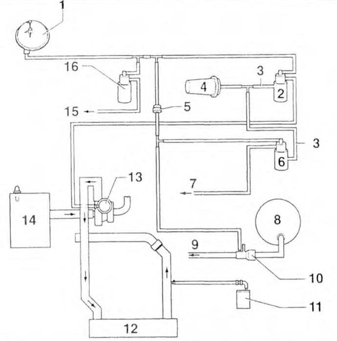
Figure 3.48a. Schematic diagram of the exhaust gas recirculation system: 1 - Vacuum tank; 2 - Boost pressure control solenoid valve; 3 - Ventilation tube; 4 - Filter; 5 - Non-return valve; 6 - EGR valve; 7 - To the EGR valve; 8 - Brake booster vacuum pump; 9 - Vacuum pump; 10 - Connection; 11 - Fuel injection system control unit; 12 - Intercooler; 13 - Exhaust manifold valve; 14 - Air filter: 15 - To the vacuum control unit of the valve in the intake manifold; 16 - Intake manifold flap control valve.
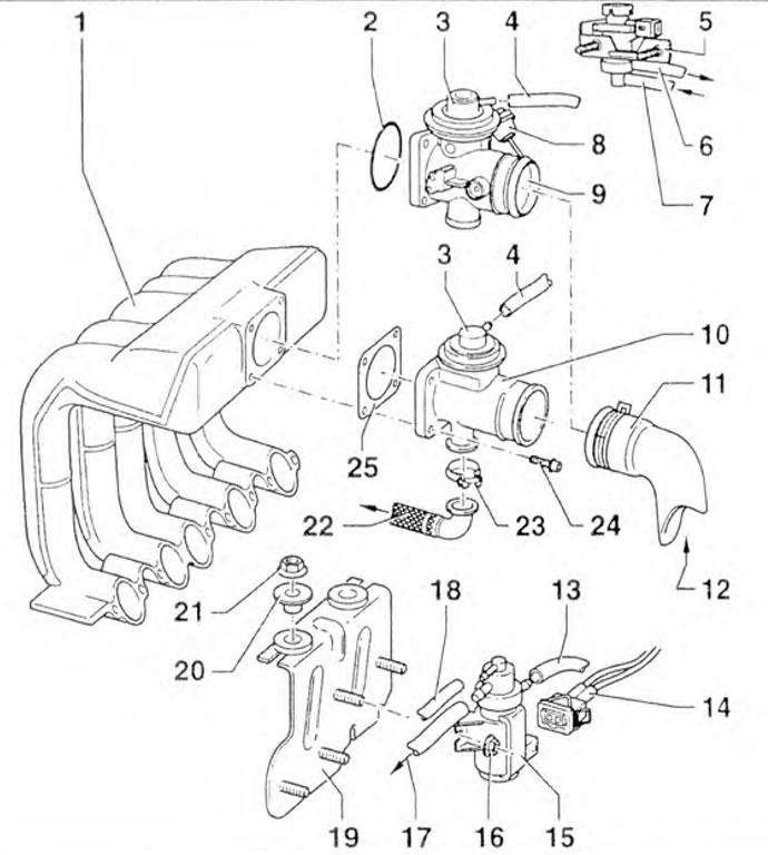
Figure 3.48b. Elements and parts of the exhaust gas recirculation system: 1 - Intake manifold; 2 - Sealing ring; 3.15- EGR valves; 4, 7, 13, 18 - Vacuum tubes; 5 - Intake manifold flap control valve; 6 - To the vacuum control unit of the valve in the intake manifold; 8 - Vacuum control element; 9, 10 - Connection of vacuum tubes; 11 - Boost air supply pipe; 12 - From the boost air supply pipe; 14 - Wiring connector; 16, 21 - Nuts; 17 - To the EGR valve; 19 - Bracket; 20 - Bushing; 22 - To the exhaust manifold; 23 - Clamp; 24 - Bolt; 25 - Gasket.
The information is posted on this resource (VWMANUAL)
Visitor comments