



Contents: Verification procedure ↓ Engines ANJ, ARA (from 06:00), BBE,…↓ On ANJ engines ↓ On ARA, VVE, BBF engines ↓ Checking the boost pressure control…↓ Vehicles with a 68-pin control unit…↓ Vehicles with 121-pin control unit…↓ On all cars ↓
1. Boost pressure is measured at full load or on a test bench. The test lasts 10 seconds.
2. Disconnect the pressure pipe (black) between the compressed air supply pipe and the fuel injection control unit from the control unit 1 (figure 3.43).
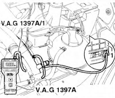
Figure 3.43. Disconnect the pressure pipe (black) between the compressed air supply pipe and the fuel injection control unit from control unit 1.
3. Connect the T-piece to the compressed air supply tube and the discharge tube.
4. Connect the VAG 1397 A/1 connecting tube with the VAG 1397 A tester and T-piece.
5. Turn on measuring level II.
6. Measure the boost pressure at full load. When testing on a bench, engage 3rd gear at 2500-3000 rpm; when testing while driving, engage 2nd gear and fully press the accelerator pedal and observe the tachometer.
7. Press the "M" key on the tester at 2500-3000 rpm and read the resulting value. Set value: 0.60-0.80 bar.
8. If the specified value is not achieved, replace the turbocharger.
9. If the boost pressure is too high and the boost pressure control valve test tube is not clogged, loosen it or release the pressure, or the turbocharger may need to be replaced if the boost pressure control valve is damaged.
Verification procedure
The boost pressure must be measured with the VAG 1551 tester throughout the entire test.
Engines ANJ, ARA (from 06:00), BBE, BBF
10. Connect the VAG 1551 tester and select "Electronic engine control" "01" The engine should idle. The display should show the following information:
- Quick data search HELP
- Select function XX
11. Press "08" to select the "Read Block of Measured Values" function and press "Q". The display should show the following information:
- Reading the measured value block HELP
- Enter group number XXX
12. Press "01" "1" to select the "Group 11" function and press "Q". The display should show the following information:
Reading measured value block 11 → 840 rpm 938 mbar 978 mbar 92%
13. Accelerate the car in 3rd gear at 1500 rpm with the accelerator pedal fully depressed. Press PRINT on the tester at 3000 rpm.
On ANJ engines
14. Set the value on the VAG 1551 tester: 1780-1970 mbar (field "3" on the display). The following information should be shown on the display:
Reading block of measured values 11 → 3090 rpm 1866 mbar 1917 mbar 62%
15. If the set value is not reached: Complete the diagnostics carefully and activate the boost pressure control solenoid valve. The display should show the following information:
- End of diagnostics →
- Boost pressure control solenoid valve
16. The solenoid valve should work and during the test the booster rod on the turbocharger should move back and forth (at least 3-4 times until the vacuum is present in the vacuum tank).
17. If the rod moves and the boost pressure does not meet the specified value, replace the turbocharger.
18. If the rod does not move because the solenoid valve is faulty: check the valve and the vacuum delivery tubes.
19. If the rod does not move despite the valve working: connect the VAG 1390 vacuum pump to the boost pressure control valve and check the ease of movement of the rod (figure 3.44).
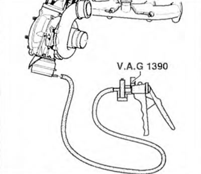
Figure 3.44. If the rod does not move despite the valve working: connect the VAG 1390 vacuum pump to the boost pressure control valve and check the ease of movement of the rod.
20. If the rod does not move easily, replace the turbocharger.
On ARA, VVE, BBF engines
21. Set the value on the 1551 tester to 1780-1950 mbar (field "3" on the display). The display should show the following information:
Reading block of measured values 11 → 3090 rpm 1866 mbar 1917 mbar 62%
22. If the specified value is not achieved: check the boost pressure control solenoid valve or replace the turbocharger.
Checking the boost pressure control solenoid valve
23. Disconnect connector 1 from solenoid valve 2 (figure 3.45).
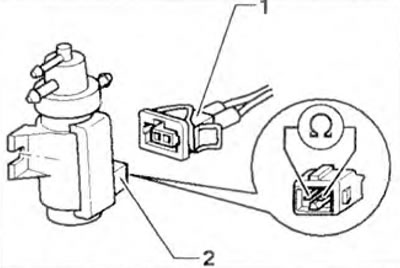
Figure 3.45. Disconnect connector 1 from solenoid valve 2.
24. Measure the resistance between the valve contacts.
Specified value:
- motors AHD, APA, VBE, BBF: 25-45 Ohm.
- aNJ motor: 15-20 Ohm.
25. If the obtained value does not correspond to the specified one, replace valve 26. If the specified value is reached: turn on the ignition. Measure the voltage between valve terminal 1 and engine ground (figure 3.46). Set value: battery voltage.
If the specified value is not reached: turn off the ignition, remove the front left turn signal and headlight.
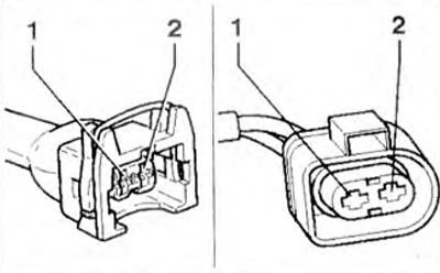
Figure 3.46. Measure the voltage between valve terminal 1 and the engine ground connection.
Vehicles with a 68-pin control unit connector
27. Connect the VAG 1598/18 tester to the control unit wiring. The engine control unit is not involved in the process.
28. Check the resistance of the wires between the tester and the connector: contact 1 + socket 68, contact 2 + socket 47. Wire resistance: max. 1.5 Ohm.
Vehicles with 121-pin control unit connector
29. Connect the VAG 1598/31 tester to the control unit wiring. The engine control unit is not involved in the process.
30. Check the resistance of the wires between the tester and the connector: contact 1 + socket 1 + 2, contact 2 + socket 62. Wire resistance: max. 1.5 Ohm.
On all cars
31. Also check the wires for short circuits between the negative and positive poles.
32. If no faults are found: disconnect the tester.
33. Replace the fuel injection control unit if necessary.
Visitor comments