



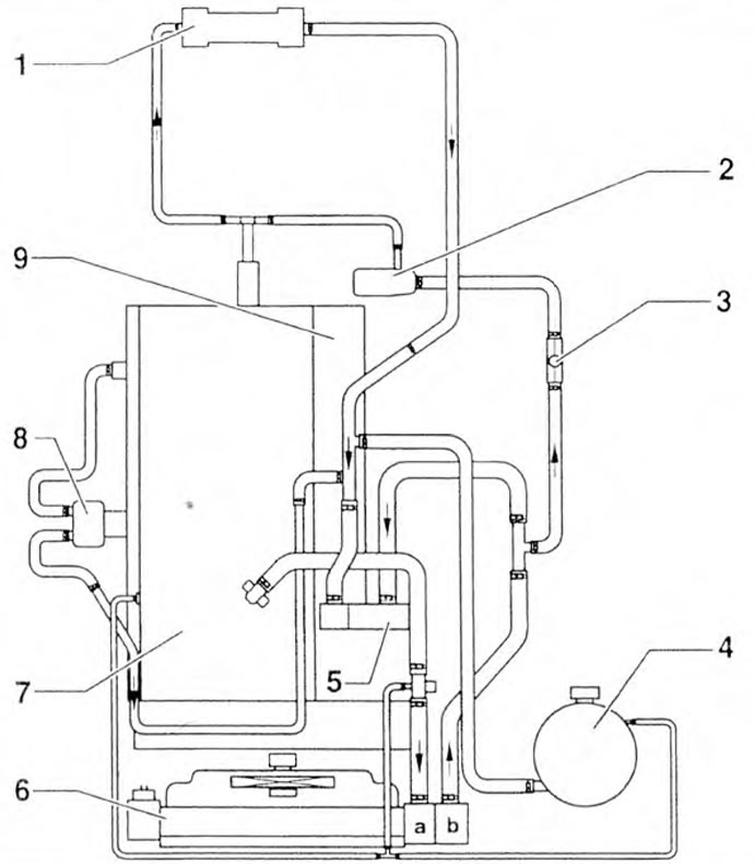
Figure 3.36a. Cooling system diagram: 1 - Heater radiator; 2 - Pump for circulating coolant during engine operation; 3 - Vacuum valve; 4 - Expansion tank; 5 - Cooling system pump; 6 - Radiator: 7 - Cylinder head; 8 - Oil radiator; 9 - Cylinder block.
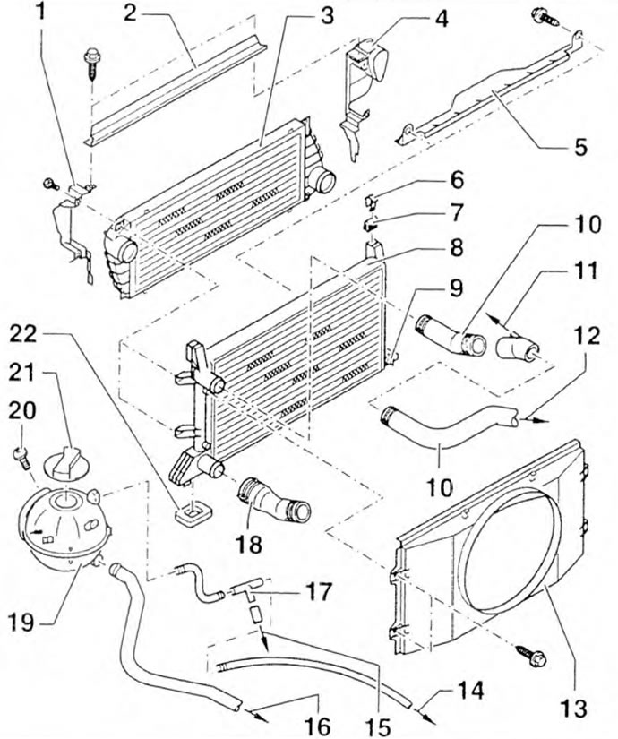
Figure 3.36b. Elements and parts of the cooling system: 1, 2, 5, 13 - Guide louvers, 3 - Intercooler (charge air intermediate cooling radiator); 4 - Air duct; 6 - Retainer; 7, 22 - Rubber supports; 8 - Radiator; 9 Drain plug; 10 - Upper cooling system hose; 11 - To the cooling system pipe; 12 - To the adapter; 14 - To the cylinder head: 15 - To the upper branch pipe of the cooling system; 16 - To the cooling system pipe; 17 - T-shaped adapter; 18 - Lower cooling system hose; 19 - Expansion tank; 20 - Bolt: 21 - Cover.
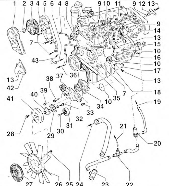
Figure 3.36c. Elements and parts of the cooling system: 1, 2, 5, 13 - Guide louvers, 3 - Intercooler (charge air intermediate cooling radiator); 4 - Air duct; 6 - Retainer; 7, 22 - Rubber supports; 8 - Radiator; 9 - Drain plug; 10 - Upper cooling system hose; 11 - To the cooling system pipe; 12 - To the adapter; 14 - To the cylinder head: 15 - To the upper branch pipe of the cooling system; 16 - To the cooling system pipe; 17 - T-shaped adapter; 18 - Lower cooling system hose; 19 - Expansion tank; 20 - Bolt; 21 - Lid.
The original article is available on the website www.VWManual.ru
Visitor comments