



2. Disconnect the wiring connector of the sender 1 (figure 3.65). Measure the resistance between the connector contacts. Set value: 80-120 Ohm
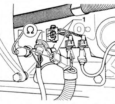
Figure 3.65. Checking the resistance between the contacts of the injector needle displacement sensor connector.
3. If the specified value is not achieved, replace the 5th cylinder injector together with the injector needle position sensor.
On vehicles with a 68-pin control unit connector
4. If the specified value is reached, connect the VAG 1598/18 tester to the engine control unit wiring harness. Check the wires between the tester and the connector for continuity: pin 1 + socket 12. pin 2 + socket 11 (figure 3.59). Specified value: max. 1.5 ohm.
5. Check the ground wire connection between the needle position sensor and the fuel injection system wiring. Specified value: max 1.5 ohm.
6. Check the wires for short circuits, short circuits to positive or negative poles.
7. If there are no faults in the wires. replace the fuel injection system control unit.
On vehicles with a 121-pin control unit connector
8. If the specified value is reached, connect the VAG 1598/31 tester to the engine control unit wiring harness. Check the wires between the tester and the socket for continuity: pin 1 + socket 109, pin 2 + socket 101 (figure 3.59). Specified value: max. 1.5 ohm.
9. Check the ground wire connection between the needle position sensor and the fuel injection system wiring. Specified value: max 1.5 ohm.
10. Check the wires for short circuits, short circuits to positive or negative poles.
11. If there are no faults in the wires, replace the fuel injection system control unit.
Visitor comments