



2. Turn off the ignition.
3. Observe the intake manifold flap adjusting lever (assistant needed).
4. The intake manifold flap should close after the ignition is turned off and then open again after approximately 3 seconds.
5. If the valve does not set to the required position, check: the damper control mechanism by moving the rod by hand; operation of the vacuum element using a hand vacuum pump; vacuum tubes for correct connection.
6. If no mechanical damage is found, check the throttle position switching valve.
7. Disconnect the wiring connector from the throttle position switching valve and measure the resistance between the valve contacts (figure 3.69). Set value: 25-45 Ohm.
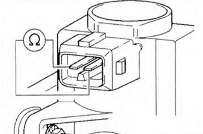
Figure 3.69. Disconnect the wiring connector from the throttle position switching valve and measure the resistance between the valve contacts.
8. If the specified value is not achieved, replace the throttle position switching valve.
9. If the set value is reached, set the multimeter to measure voltage and connect it to contacts 1 and 2 of the valve connector (figure 3.70).
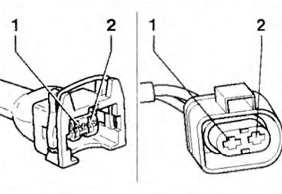
Figure 3.70. If the set value is reached, set the multimeter to measure voltage and connect it to contacts 1 and 2 of the valve connector.
10. Start the engine and let it idle. Set value: battery voltage.
11. Turn off the ignition.
12. The voltage should drop to 0 after about 3 seconds.
On vehicles with a 68-pin control unit connector
13. If the voltage does not change, connect the VAG 1598/18 tester to the engine control unit wiring harness. Check the wires between the tester and the socket for continuity: pin 1 + socket 68, pin 2 + socket 54 (figure 3.59). Specified value: max. 1.5 ohm.
14. Check the connector wires for short circuit.
Set value: ∞ Ohm.
15. If there are no faults in the wires, replace the fuel injection system control unit.
On vehicles with a 121-pin control unit connector
16. If the voltage does not change, connect the VAG 1598/31 tester to the engine control unit wiring harness. Check the wires between the tester and the connector for continuity: pin 1 + sockets 1 and 2, pin 2 + socket 81 (figure 3.59).
Specified value: max 1.5 ohm
17. Check the connector wires for short circuit.
Set value: ∞ Ohm.
18. If there are no faults in the wires, replace the fuel injection system control unit.
Visitor comments