
The inner CV joint can be ball bearing or roller, which is also called «tripod».
Attention! When performing all work, during which it is necessary to disconnect the drive shaft from the hub or from the gearbox, the shaft should be pulled by the CV joint.
Attention! After dismantling the drive shaft, the vehicle must not stand on its wheels, because due to the lack of axial load, damage to the hub bearing occurs.
Attention! It is not allowed to move the car after removing the drive shaft. If necessary, instead of the drive shaft, you can install the shank of the outer CV joint into the hub and screw in the hub bolt with a force of 120 Nm.
Drive shaft with CV joint «tripod» AAR 3300i
1. Remove the hub bolt.
Attention! At the time of the final unscrewing of the hub bolt, the car must not be on wheels.
2. Mark the direction of rotation of the wheel by chalking an arrow on the side of the wheel.
3. Unscrew the wheel mounting bolts and remove it from the hub.
4. Remove the engine mudguard, see relevant chapter.
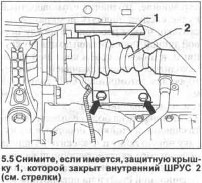
5. Right drive shaft. Remove, if any, the protective cover 1, which covers the inner CV joint 2 (see arrows in illustration).
6. Unscrew the bolts with which the inner CV joint 1 is attached to the flange 2 on the gearbox or intermediate shaft (see illustration).
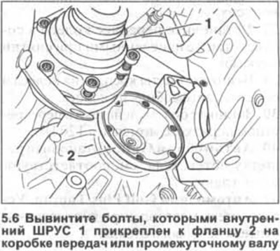
To unscrew the bolts, a multi-faceted socket wrench is required, eg HAZET 990 Lg-8/10.
7. Slide the outer CV joint shank out of the hub, holding it by the body, not the shaft.
Attention! If the drive shaft is tightly seated in the hub, then press it out with a puller, for example, HAZET2515-1.
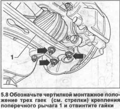
8. Mark the mounting position of the three nuts with a scriber (see arrows in illustration) securing the transverse arm 1 and unscrew the nuts.
9. Disconnect the steering knuckle and articulated arm from the transverse arm.
10. Completely remove the drive shaft from the hub.
Installation
Attention! Remove any corrosion or sealant residue from the threads on the shank, as well as from its splines and splines on the hub.
11. Insert the drive shaft shank into the hub.
12. Attach the pivot arm to the transverse arm, being careful not to damage the ball joint cap or twist it.
13. Screw new self-locking nuts onto the ball bearing pins of the lever and tighten them with a force of 75 Nm.
14. Bolt the inner CV joint to the gearbox flange or to the intermediate shaft. Tighten the mounting bolts in two passes.
- 1st pass 10 Nm;
- 2nd pass. Bolts M8 40 Nm;
- 2nd pass. Bolts M10 70 Nm.
15. Reinstall the engine mudguard, see relevant chapter.
16. Screw in the hub bolt. When screwing in the bolt, the vehicle must not be on wheels.
17. Reinstall the removed wheel in accordance with the marked marks and screw in the wheel bolts.
18. Lower the vehicle onto the wheels and tighten the wheel bolts to 120 Nm in a criss-cross pattern.
Drive shaft with CV joint «tripod» AAR 2600i
Attention! Drive shaft with internal CV joint «tripod» AAR 2600i is not flanged to the gearbox. The CV joint shank is inserted into the corresponding slotted hole on the gearbox.
Removing
19. Remove the hub bolt.
Attention! At the time of the final unscrewing of the hub bolt, the car must not be on wheels.
20. Mark the direction of rotation of the wheel by chalking an arrow on the side of the wheel.
21. Unscrew the wheel mounting bolts and remove it from the hub.
22. Remove the engine mudguard, see relevant chapter.
23. Mark with a scriber the mounting position of the three transverse arm fastening nuts and unscrew the nuts.
24. Disconnect the pivot arm from the transverse arm.
25. Remove the drive shaft from the hub.
Attention! If the drive shaft is tightly seated in the hub, then press it out with a puller, for example, HAZET 2515-1.
26. Fix the power shaft disconnected from a nave to a body or details of a suspension bracket. If left loose, shaft deflection will damage the internal CV joint.
27. Insert pry bar 1 between the gearbox housing and inner CV joint 2 and release the CV joint from the box by hitting the mount with a hammer (see illustration).
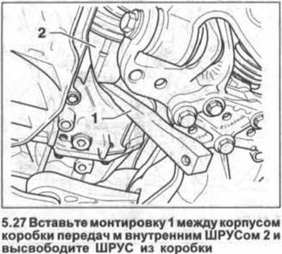
Attention! After the drive shaft is disconnected, oil will flow out of the gearbox. Substitute an appropriate container under the box, and close the hole itself with a suitable stopper, for example, with a clean rag.
Installation
28. Clean the splines and threads of the drive shaft shank, as well as the spline hole in the gearbox and in the hub, removing possible rust and other contaminants, and lubricate them with gear oil.
29. Using a screwdriver, remove the circlip 1 from the shank of the drive shaft attached to the gearbox (see illustration).
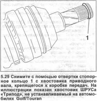
30. Fit a new circlip to the shank, being careful not to stretch it.
31. Remove the plug that closed the hole on the gearbox and insert the drive shaft shank into the slotted hole on the gearbox. At the same time, be careful not to damage the drive shaft seal in the gearbox.
32. Press on the drive shaft so that its circlip locks into the gearbox.
Attention! It is not allowed to drive the drive shaft into the gearbox with a hammer.
33. Check the tightness of the shaft in the gearbox by pulling on the CV joint housing.
34. Install the other end of the drive shaft into the hub.
35. Attach the pivot arm to the transverse arm, being careful not to damage the ball joint cap or twist it.
36. Screw new self-locking nuts onto the fingers of the ball bearings of the lever and tighten them with a force of 75 Nm.
37. Reinstall the engine mudguard, see relevant chapter.
38. Screw in the hub bolt. When screwing in the bolt, the vehicle must not be on wheels.
39. Reinstall the removed wheel in accordance with the marked marks and screw in the wheel bolts.
40. Lower the vehicle onto the wheels and tighten the wheel bolts to 120 Nm in a criss-cross pattern.
Intermediate shaft
Depending on the model of the car, the right drive shaft may consist of an intermediate shaft, which is attached to the gearbox, and the axle shaft itself.
This ensures the transmission of torque without torsional vibrations. The axle shaft and the intermediate shaft are flanged to each other.
Removing
41. Remove the right axle shaft 1 (see illustration).
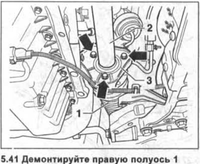
42. Unscrew the three bolts securing the intermediate support 3 shaft (see arrows in illustration 5.41).
43. Disconnect the intermediate shaft 2 from the gearbox (see illustration 5.41).
Installation
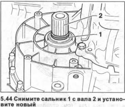
44. Remove oil seal 1 from shaft 2 and install a new one (see illustration).
45. Clean the splines and threads of the drive shaft shank, as well as the spline hole in the gearbox and in the hub, removing possible rust and other contaminants, and lubricate them with gear oil.
46. Screw in the three bolts of the intermediate shaft support and tighten them with a force of 20 Nm.
47. Reinstall the right axle shaft.
Visitor comments